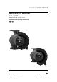
GRUNDFOS INSTRUCTIONS GRUNDFOS MAGNA Series 2000 MAGNA 40-120, 65-120, 65-60 Installation and operating instructions
LIMITED WARRANTY Products manufactured by GRUNDFOS PUMPS CORPORATION (Grundfos) are warranted to the original user only to be free of defects in material and workmanship for a period of 24 months from date of installation, but not more than 30 months from date of manufacture. Grundfos' liability under this warranty shall be limited to repairing or replacing at Grundfos' option, without charge, F.O.B. Grundfos' factory or authorized service station, any product of Grundfos' manufacture.
GRUNDFOS MAGNA Series 2000 MAGNA 40-120, 65-120, 65-60 Installation and operating instructions Notice d’installation et d’entretien 4 25 3
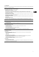
CONTENTS 1. 2. 3. 3.1 4. 4.1 4.2 4.3 4.4 5. 5.1 5.2 6. 7. 7.1 7.2 7.3 7.4 7.5 7.6 7.7 7.8 7.9 7.10 7.11 7.12 8. 8.1 8.2 8.3 8.4 8.5 8.6 8.7 8.8 9. 10. 11. 12. Symbols used in this document General description Applications Pumped liquids Installation Changing the control box position Two pumps in parallel Check valve Frost protection Electrical connection Supply voltage Connection diagram Start-up Functions Control modes Selection of control mode Automatic night-time duty Constant-curve duty Max. or min.
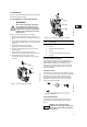
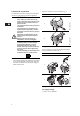
4. Installation Arrows on the pump housing indicate the liquid flow direction through the pump. 4.1 Changing the control box position WARNING! Change the control box position as follows: 1. Remove the inspection screw (1) and the four Allen screws (6 mm) (2) in the stator housing, see fig. 1. 2. Lift off the stator housing (3). Keep the rotor (4) in place using a suitable tool, e.g. a T-key (M8) (5), see fig. 2. 3. Check that the O-ring (6) is intact. A defective O-ring must be replaced. 4.
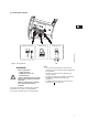
5. Electrical connection The electrical connection and protection should be carried out in accordance with local regulations. Open the control box cover as shown in fig. 4. Step Action If the pump is connected to an electric installation where an earth leakage circuit breaker (ELCB) is used as additional protection, this circuit breaker must trip out when earth fault currents with DC content (pulsating DC) occur.
5.2 Connection diagram Supply connection Signal output Start/stop input 1 2 3 L N Fig. 6 NC NO NC NO C C S T O P TM02 0235 1007 8 7 Wiring diagram WARNING! • • Wires connected to – supply terminals, – outputs NC, NO, C and – start/stop input must be separated from each other and from the supply by reinforced insulation. All wires connected to a terminal block must be tied up at the terminals.
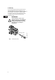
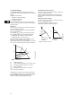
6. Start-up Do not start the pump until the system has been filled with liquid and vented. Furthermore, the required minimum inlet pressure must be available at the pump inlet, see section 11. Technical data. The system cannot be vented through the pump. The pump can be vented by slackening the inspection screw. WARNING! Inspection screw Fig. 7 8 Venting the pump TM03 8912 2707 If the inspection screw is to be loosened, see fig.
7. Functions Most functions can be selected on the pump control panel. However, some functions can only be selected with the R100 or via expansion modules. On the pump control panel, see fig. 13, page 15: • AUTOADAPT (factory setting) Recommended for most heating installations. During operation, the pump automatically makes the necessary adjustment to the actual system characteristic. This setting ensures minimum energy consumption and noise level which reduces operating costs and increases comfort.
A GRUNDFOS MAGNA pump can be set to the control mode which is most suitable for the individual system. Possible control modes: • AUTOADAPT (factory setting) • Proportional pressure • Constant pressure. Each of the control modes can be combined with automatic night-time duty, see section 7.3 Automatic night-time duty. AUTOADAPT To be set on the control panel or with the R100, see section 8. Setting the pump. The control mode AUTOADAPT continuously adapts the pump performance.
7.2 Selection of control mode Select this control mode System type Description Typical heating systems Grundfos recommends to let the pump remain in AUTOADAPT mode. This ensures optimum performance at the lowest possible energy consumption. 1.
7.3 Automatic night-time duty 7.6 Temperature influence To be set on the control panel or with the R100, see section 8. Setting the pump. Once automatic night-time duty has been activated, the pump automatically changes between normal duty and night-time duty (duty at low performance). Changeover between normal duty and night-time duty is dependent on the supply-pipe temperature.
7.7 External start/stop The pump can be started or stopped via an external potential-free contact or a relay connected to terminals 7 and 8, see section 5.2 Connection diagram. Functional diagram: Start/stop input Start/stop input H Normal duty Q H Stop Q 7.8 Signal relay The pump incorporates a signal relay, terminals 1, 2 and 3, for a potential-free fault and operating signal. The function of the signal relay, fault signal (factory setting) or operating signal, is set with the R100.
For the setting of the pump, use: • control panel • R100 remote control • bus communication (not described in detail in these instructions, contact Grundfos). The table shows the application of the individual operating units and in which section the function has been described. 7.11 GENI module The GENI module offers the following functions: • External analog 0-10 V control • External forced control • Bus communication via GENIbus • Control of two pumps in parallel.
8.2 Control panel 8.2.1 Control mode setting Description of function, see section 7.1 Control modes. To change the control mode, press , pos. 3, according to this cycle: WARNING! At high liquid temperatures, the pump may be scalding hot, only the buttons should be touched to avoid burns. AUTO The control panel, fig.
8.2.2 Setpoint setting Set the setpoint of the pump by pressing or when the pump has been set to proportionalpressure control, constant-pressure control or constant-curve duty. The light fields, pos. 5, on the control panel indicate the setpoint set. 8.2.4 Setting to min. curve duty Description of function, see section 7.5 Max. or min. curve duty. To change over to the min. curve, press continuously until "MIN" illuminates, see fig. 18.
8.4 R100 display overview The R100 displays are divided into four parallel menus, see fig. 19: 0. GENERAL, see operating instructions for R100 1. OPERATION 2. STATUS 3. INSTALLATION The number stated at each individual display in fig. 19 refers to the section in which the display is described. This display appears only once, i.e. when the R100 gets contact with the pump. 0. GENERAL 1. OPERATION 2. STATUS 3. INSTALLATION 8.5.1 8.6.1 8.7.1 8.5.2 8.6.2 8.7.2 8.5.3 8.6.3 8.7.3 8.5.4 8.6.4 8.7.
8.5 Menu OPERATION 8.5.3 Fault indications When the communication between the R100 and the pump has been established, "Contact with" appears in the display. When the "arrow down" on the R100 is pressed, menu OPERATION appears. Note The display "Contact with" appears only once, i.e. when the R100 gets contact with the pump. 8.5.1 Setpoint This display depends on the control mode selected in the display "Control mode" in menu INSTALLATION.
8.6 Menu STATUS 8.6.5 Liquid temperature The displays appearing in this menu are status displays only. It is not possible to change or set values. The actual values in the display are indicative and based on estimation. 8.6.1 Actual setpoint The actual temperature of the pumped liquid. 8.6.6 Power input and power consumption Field "Actual setpoint": Actual setpoint of pump.
8.7 Menu INSTALLATION This menu shows the settings that should be considered when installing the pump. In the case of temperature influence, the pump must be installed in the supply pipe. It is possible to choose between maximum temperatures of 122 °F (50 °C) and 176 °F (80 °C). 8.7.1 Control mode Description of function, see section 7.1 Control modes or section 7.4 Constant-curve duty.
8.8 Priority of settings The external forced-control signals will influence the settings available on the pump control panel and with the R100. However, the pump can always be set to max. curve duty or to stop on the pump control panel or with the R100. If two or more functions are activated at the same time, the pump will operate according to the setting with the highest priority. The priority of the settings is as shown in the table.
9. Fault finding chart WARNING! Before removing the control box cover, make sure that the electricity supply has been switched off for at least 5 minutes. The pumped liquid may be scalding hot and under high pressure. Before any removal or dismantling of the pump, the system must therefore be drained or the isolating valves on either side of the pump must be closed. Indicator light is off. Indicator light is on. Indicator light is flashing. Indicator lights Fault Cause Remedy The pump is not running.
Indicator lights Fault Cause Remedy Noise in the system. Air in the system. Vent the system. The flow is too high. Reduce the setpoint and possibly change over to AUTOADAPT or constant pressure. The pressure is too high. Reduce the setpoint and possibly change over to AUTOADAPT or proportional pressure. Green Red Noise in the pump. Note Air in the pump. Vent the pump. The inlet pressure is too low. Increase the inlet pressure and/or check air volume in the expansion tank (if installed).
11. Technical data Pump inputs and outputs Supply voltage 1 x 230 ± 10 %, 50/60 Hz. Motor protection The pump requires no external motor protection. Signal output Internal potential-free changeover contact. Maximum load: 250 V, 2 A, AC1. Minimum load: 5 V, 100 mA. Screened cable, depending on signal level. Input for external start/stop External potential-free switch. Contact load: 5 V, 10 mA. Screened cable. Loop resistance: Maximum 130 Ω. Enclosure class IP 44. Insulation class F.
D7 H3 H2 B5 B4 H4 B6 B3 B7 D1 D2 D3 TM03 9055 3207 1/4" Rp NPT 1/4 M L3 B1 L1 B2 H1 D4 D6 D5 MAGNA 40-120 GF 15/40 [Inch/pouce] [mm] L1 8 1/2 216 L3 4 1/4 108 B1 3 1/16 77 B2 4 1/2 115 B3 2 15/16 75 B4 3 1/8 80 B5 3 3/4 or 3 1/8* 96 or 80* B6 5 1/2 140 B7 4 5/16 110 H1 2 11/16 68 H2 9 1/2 242 H3 12 3/16 310 H4 3 3/4 96 D1 1 9/16 40 D2 2 15/16 75 D3 3 1/8 or 3 7/16 80/87 D4 4 3/4 120 D5 1/2 12 D6 1 15/16 49 D7 2 3/8 60 * 3 1/8" (8
D4 H3 H2 B5 D1 D5 B4 H4 1/4" NPTNPT 1/4 B6 D2 B3 B7 MAGNA 65-120 MAGNA 65-60 GF 53 GF 53 [Inch/pouce] [mm] [Inch/pouce] [mm] L1 11 1/2 292 11 1/2 292 L3 5 3/4 146 5 3/4 146 B1 3 1/16 77 3 1/16 77 B2 4 15/16 125 4 15/16 125 B3 3 7/16 88 3 7/16 88 B4 4 1/8 104 4 1/8 104 B5 3 3/4 or 3 1/8* 96 or 80* 3 3/4 or 3 1/8* 96 or 80* B6 5 1/2 140 5 1/2 140 B7 4 5/16 110 4 5/16 110 H1 3 1/4 82 3 1/4 82 H2 9 15/16 252 9 15/16 252 H3 13 1/8 334 13
Connection diagram without optional expansion modules Diagramme montrant la connexion sans l'utilisation d'un module d'extension optionnel MAGNA 40-120, 65-120, 65-60 NC NO C 1 2 3 8 7 TM02 0477 1004 L N S T O P 49
Connection diagram with optional GENI module with no external stop function Diagramme montrant la connexion en utilisant le module GENI optionnel sans fonction d'arrêt externe L N NC NO C 1 2 3 S T O P 8 7 A Y B MIN MAX 10 V MAGNA 40-120, 65-120, 65-60 with GENI module (avec module GENI) X Q Z 4 5 6 7 9 10 11 12 21 22 23 Max. OD: Max. ø7 TM02 0478 1004 0.
Connection diagram with optional GENI module with external stop function Diagramme montrant la connexion en utilisant le module GENI optionnel avec fonction d'arrêt externe NC NO C 1 2 3 A Y B X Q Z 4 5 6 7 9 10 11 12 21 22 23 Max. OD: Max. ø7 0.
Wiring diagram for two pumps in parallel (master) Diagramme de connexion pour deux circulateurs en parallèle (maître) L N NC NO C 1 2 3 S T O P 8 7 A Y B MIN MAX 10 V MAGNA 40-120, 65-120, 65-60 with GENI module (avec module GENI) X Q Z 4 5 6 7 9 10 11 12 21 22 23 Max. OD: Max. 0.
Wiring diagram for two pumps in parallel (slave) Diagramme de connexion pour deux circulateurs en parallèle (esclave) NC NO C 1 2 3 8 7 A Y B X Q Z 4 5 6 7 9 10 11 12 21 22 23 Max. OD: Max. 0.
54
U.S.A. Canada México GRUNDFOS Pumps Corporation 17100 West 118th Terrace Olathe, Kansas 66061 Phone: +1-913-227-3400 Telefax: +1-913-227-3500 GRUNDFOS Canada Inc. 2941 Brighton Road Oakville, Ontario L6H 6C9 Phone: +1-905 829 9533 Telefax: +1-905 829 9512 Bombas GRUNDFOS de México S.A. de C.V. Boulevard TLC No. 15 Parque Industrial Stiva Aeropuerto Apodaca, N.L.C.P. 66600 Phone: +52-81-8144 4000 Telefax: +52-81-8144 4010 Addresses revised 22.09.
Being responsible is our foundation Thinking ahead makes it possible Innovation is the essence L-MAG-TL-01 96746689 0907 www.grundfos.