
TP40-80/2 Products Guide
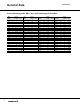
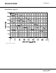
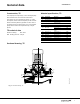
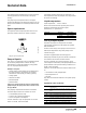
Table Of Contents
- Mission
- General data
- Cross reference guide: B&G, Taco and Armstrong to Grundfos
- Performance range, TP
- Product range, TP
- Type key, TP
- Applications
- Construction, TP
- TP technical data
- Material specification, TP
- Sectional drawing, TP
- Motor
- Pump
- Surface treatment
- Motor stool
- Pump shaft
- Coupling
- Impeller
- Shaft seal
- Space requirements
- Pumped liquids
- Liquid temperature
- List of pumped liquids
- Legend for notes in the list
- Performance curves
- Data charts
- Submittal data sheet
- Further product documentation

General data
VersaFlo® TP
8
Motor
The motor is a totally enclosed, fan-cooled standard
motor with main dimensions to NEMA standards.
Mounting designation: NEMA C FACE
Enclosure class: TEFC; (ODP) optional
Insulation class: F
Ambient temperature: Max. 104°F.
Pump
In-line cast iron or bronze spiral pump housing.
Flange dimensions for USA are according to Industry
and or ANSI Standard.
The flanges have ¼ NPT pressure gauge tappings.
Tapped holes are provided on the underside of the
pumps. These holes can be used for fitting the pump to
a base plate, bracket or the like by means of hexagon
screws. The pump housing is provided with a
replaceable stainless steel/Teflon neck ring. The ring
reduces to a minimum the amount of liquid running from
the discharge side of the impeller to the suction side.
Surface treatment
The pump housing and the motor stool are
electrocoated .
The treatment includes:
1. Alkaline cleaning.
2. Pre-treatment with zinc phosphate coating.
3. Cathodic electrocoating (epoxy).
Coating thickness: 15-20 μm.
4. Curing of paint film at 200-250°C.
Motor stool
The motor stool forms connection between the pump
housing and the motor, and is equipped with a manual
air vent screw for venting of the pump housing and the
shaft seal chamber. The sealing between motor stool
and pump housing is either an O-ring or a flat gasket.
The central part of the motor stool is provided with
guards for protection against shaft and coupling.
The dimensions of the motor side flange of the motor
stool are according to NEMA.
Pump shaft
The shaft is a cylindrical ∅16 mm stainless steel shaft.
The coupling end of the shaft has a hole for the coupling
shaft pin.
Coupling
The coupling is a two-piece, inelastic sintered metal
coupling secured with four hexagon socket head
screws.
Impeller
The impeller is made of stainless steel, AISI 304 SS.
As the impeller is made of stainless steel sheet, it can
be pressed into the correct hydraulic form.
Shaft seal
The pumps are fitted as standard with a single,
unbalanced tungsten carbide/carbon rubber bellows
shaft seal in a 16 mm diameter size with EPDM
elastomer (BUBE). The tungsten carbide/carbon shaft
seal has a wide range of applications and is especially
suitable where there is a risk of dry running and in case
of high temperatures.
The tungsten carbide/carbon shaft seal is not suitable
for liquids containing abrasive particles, as the carbon
parts will be worn down. In that case a tungsten
carbide/ tungsten carbide seal is recommended.
Optional shaft seals available:
• unbalanced tungsten carbide/tungsten carbide
O-ring shaft seal with EPDM elastomer (AUUE).
And for glycol/water mixtures:
The circulation of liquid through the duct of the air vent
screw ensures lubrication and cooling of the shaft seal.
Fig. 3
TP pumps can be installed in horizontal and vertical
pipes.
Note: The motor must never point downwards.
Unbalanced reduced face tungsten
carbide/tungsten carbide O-ring shaft
seal with EPDM elastomers (RUUE).
TM00 2265 4696