
User Guide

9
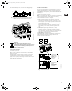
5.1 Menu OPERATION
When communication between the R100 and the pump has been
established, the first display in this menu will appear.
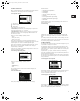
5.1.1 Setpoint setting
Setpoint set
Actual setpoint
Actual value
In this display, the setpoint is set.
In controlled-operation mode, the setting range is equal to the
sensor measuring range, e.g. 0 to 25 psi.
In uncontrolled-operation mode, the setpoint is set in % of the
maximum performance. The setting range will lie between the
min. and max. curves.
Select one of the following operating modes:
• Stop,
• Min. (min. curve),
• Max. (max. curve).
If the pump is connected to an external setpoint signal, the
setpoint in this display will be the maximum value of the external
setpoint signal, see section 7. External setpoint signal.
If the pump is controlled via external signals (Stop, Min. curve or
Max. curve) or a bus, this will be indicated in the display if
setpoint setting is attempted.
In this case, the number of possible settings will be reduced, see
section 16. Priority of settings.
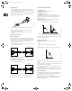
5.1.2 Setting of operating mode
Select one of the following operating modes:
• Stop,
• Min.,
• Normal (duty),
• Max.
The operating modes can be selected without changing the
setpoint setting.
5.1.3 Fault indications
If the pump is faulty, the cause will appear in this display.
Possible causes:
• Too high motor temperature,
• Undervoltage,
• Overvoltage,
• Too many restarts (after faults),
• Overload,
• Sensor signal outside signal range,
• Setpoint signal outside signal range,
• Other fault.
A fault indication can be reset in this display if the cause of the
fault has disappeared.
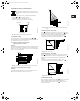
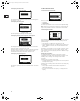
5.1.4 Alarm log
If faults have been indicated, the last five fault indications will
appear in the alarm log. “Alarm log 1” shows the newest/latest
fault.
The example shows the fault indication “Undervoltage”, the fault
code and the number of minutes the pump has been connected to
the electricity supply after the fault occurred.
5.2 Menu STATUS
The displays appearing in this menu are status displays only. It is
not possible to change or set values.
The displayed values are the values that applied when the last
communication between the pump and the R100 took place. If a
status value is to be updated, point the R100 at the control panel
and press “OK”.
If a parameter, e.g. speed, should be called up continuously,
press “OK” constantly during the period in which the parameter in
question should be monitored.
The tolerance of the displayed value is stated under each display.
The tolerances are stated as a guide in % of the maximum values
of the parameters.
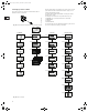
5.2.1 Display of actual setpoint
Tolerance: ±2%
This display shows the actual setpoint and the external setpoint in
% of the range from minimum value to the setpoint set, see
section 7. External setpoint signal.
5.2.2 Display of operating mode
This display shows the actual operating mode (Stop, Min., Normal
(duty) or Max.). Furthermore, it shows where this operating mode
was selected (R100, Pump, BUS or External).
Grundfos.bk Page 9 Thursday, November 11, 2010 11:21 PM