
User Guide

6
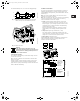
2.5 Signal cables
• Use shielded cables having a cross-sectional area of min.
0.5 mm² and max. 1.5 mm² for external on/off switch, digital
input, setpoint and sensor signals.
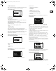
• The shields of the cables must be connected to frame at both
ends with good frame connection. They must be as close as
possible to the terminals, fig. 5.
Fig. 5 Stripped cable with shield and wire connection
• Screws for frame connections must always be tightened
whether a cable is fitted or not.
• The wires in the pump terminal box must be as short as
possible.
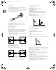
2.6 Bus connection cable
2.6.1 New installations
For the bus connection a shielded 3-core cable having a cross-
sectional area of min. 0.5 mm² and max. 1.5 mm² must be used.
• If the pump is connected to a unit with a cable clamp which is
identical to the one on the pump, the screen must be
connected to this cable clamp.
• If the unit has no cable clamp as shown in fig. 6, the screen is
left unconnected at this end.
Fig. 6 Connection with shielded 3-core cable
2.6.2 Replacing an existing pump
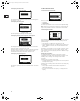
• If a shielded 2-core cable is used in the existing installation, it
must be connected as shown in fig. 7.
Fig. 7 Connection with shielded 2-core cable
If a shielded 3-core cable is used in the existing installation,
follow the instructions in section 2.6.1 New installations.
3. E-circulator series 1000
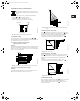
3.1 Control modes
E-pumps can be set to two control modes, i.e:
• controlled-operation or
• uncontrolled-operation.
In controlled-operation mode, the pump will adjust its
performance to the desired setpoint for the control parameter
(pressure, differential pressure, temperature, differential
temperature or flow).
In uncontrolled-operation mode, the pump will operate
according to the constant curve set.
Fig. 8 Pump in controlled-operation mode (differential
pressure control) and in uncontrolled-operation mode
The pumps have been factory-set to uncontrolled operation, see
section 3.3 Factory setting.
3.2 Operating modes
The following operating modes can be selected:
•Stop,
•Min.,
• Normal (controlled or uncontrolled operation),
•Max.
The operating modes can all be set on the pump control panel.
Fig. 9 Min. and max. curves
The min. curve can be used in periods in which a minimum flow is
required.
The max. curve can for instance be used in connection with the
venting procedure during installation.
If the electricity supply to the pump is disconnected, the pump
setting will be stored.
The remote control R100 offers additional possibilities of setting
and status displays, see section 5. Setting by means of R100.
3.3 Factory setting
The pumps have been factory-set to uncontrolled operation.
The setpoint value corresponds to 100% of the maximum pump
performance (see data sheet for the pump).
Other pump settings are marked with bold-faced type under each
individual display in sections 12.1 Menu OPERATION and
5.3 Menu INSTALLATION.
TM02 1325 0901TM02 8841 0904TM02 8842 0904
A
Y
B
A
Y
B
1
2
3
1
2
3
Pump
A
Y
B
A
Y
B
1
2
1
2
Pump
TM00 7668 0404TM00 5547 0995
Q
H
set
H
Q
H
Controlled operation
Uncontrolled operation
Q
H
Max.
Min.
Grundfos.bk Page 6 Thursday, November 11, 2010 11:21 PM