
Install Instructions


8
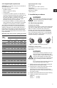
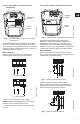
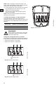
3.4.3 VersaFlo UPS 3 x 460 V and 575 V
terminal box
Fig. 8 VersaFlo UPS 3 x 460 V and 575 V
terminal box
All VersaFlo UPS pumps with three-phase x 460 V
and 575 V terminal boxes (fig. 8) come with a special
two-speed terminal box. The speed is changed by
the orientation of the jumpers as shown on page 10.
All pumps are equipped with an internal thermal
overload switch (terminals P1 and P2) to be con-
nected to external contactor.
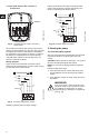
Wiring diagrams
Figure 9 shows the electrical connections when
using an external changeover contact (safety circuit)
for start/stop push button station.
Fig. 9 External changeover contact
Auxiliary contacts rated for supply voltage.
Figure 10 shows the electrical connections when
using external impulse contacts (momentary con-
tacts) for start/stop push button station.
Fig. 10 External impulse contacts
4. Starting the pump
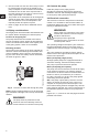
4.1 Vent the piping system
After the pump has been installed and the electrical
connections made, the piping system must be
vented.
CAUTION: Never operate the pump dry - the system
must first be filled with liquid and vented.
NOTE: Do not vent the piping system through the
pump.
Instead, follow these steps:
1. Fill and pressurize the system with liquid, and
vent all trapped air from the piping by suitable
means.
2. If any isolation valves are used, make sure they
are OPEN.
TM03 7739 4806TM03 7738 5106
L1
L2
L3
P1
P2
T6
T4
T5
T1
T2
T3
Jumpers
K
K
L3
L2
L1
Start/stop
L3
L1
L2
P1
P2
T3 T2 T1
TM03 7737 4806
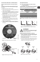
WARNING!
If the vent screw is to be loosened, care
should be taken to ensure that the escap-
ing scalding hot liquid does not cause
personal injury or damage to components
(see fig. 12).
L3
L1
L2
K
K
L3
L2
L1
Start
K
Stop
P1
P2
T3 T2
T1