
Install Instructions


7
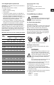
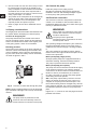
3.4.1 VersaFlo UPS 1 x 115 V and 1 x 230 V
terminal box
Fig. 3 VersaFlo UPS 1 x 115 V and 1 x 230 V
terminal box
All VersaFlo UPS single-phase pumps come with a
protection module and a speed switch as shown in
fig. 3. All pumps are equipped with built-in, automatic
resetting, thermal overload protection. The pump is
protected at all three speeds.
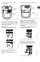
Wiring diagrams
Figure 4 shows the electrical connections for
a single-phase pump with protection module.
Fig. 4 1 x 115 V and 1 x 230 V supply
NOTE: Provide electrical disconnect and current
protection as per local electrical codes.
K = External contactor sized to FL and LR pump
current.
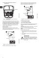
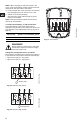
3.4.2 VersaFlo UPS 3 x 208-230 V terminal box
Fig. 5 VersaFlo UPS 3 x 208-230 V terminal box
All VersaFlo UPS pumps with three-phase x
208-230 V come with a standard module and a
speed switch as shown in fig. 5. All pumps are
equipped with an internal thermal overload switch
(terminals T1 and T2, to be connected to an external
contactor) to protect the pump at all three speeds.
Wiring diagrams
Figure 6 shows the electrical connections when
using an external changeover contact (safety circuit)
for start/stop push button station.
Fig. 6 External changeover contact
Auxiliary contacts rated for supply voltage.
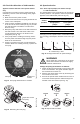
Figure 7 shows the electrical connections when
using external impulse contacts (momentary con-
tacts) for start/stop push button station.
Fig. 7 External impulse contacts
TM03 7744 4806TM03 7743 4806
Protection
module
Speed
switch
L1 L2
1 x 115 V supply
1 x 230 V supply
TM03 7742 4806TM03 7892 5106TM03 7740 4806
Standard
module
Speed
switch
K
K
Stop/Start
L1L2L3T2T1
L1L2L3
K
K
K
Stop
Start
L1L2L3T2T1
L1L2L3