
Install Instructions


10
NOTE: When changing to and from speed 1, the
cover of the speed switch module must be removed
and fitted on the other side of the switch.
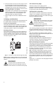
4. Fit the terminal box cover back onto the terminal
box and tighten the four screws in the cover.
5. Switch on the electrical supply.
Check that the green indicator light is perma-
nently on or flashing.
NOTE: The speed switch module must never be
used as an on/off switch.
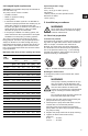
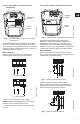
4.3.2 Two-speed pumps, 3 x 460 V and 575 V
The speed setting in the terminal box can be
changed to two positions. The speed in the two posi-
tions appears in the table below (also see fig. 13 on
page 9).
Change the pump performance as follows:
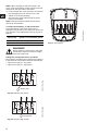
The speed is changed by the position of the jumpers
in the terminals. The jumpers are fitted according to:
• figure 15 for speed 1 - low speed
• figure 16 for speed 2 - high speed.
Fig. 15 Speed 1 (low speed)
Fig. 16 Speed 2 (high speed)
Fig. 17 Terminal box
Speed step Speed in % of maximum speed
1 approx. 75%
2 100%
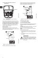
WARNING!
Never make any connections in the pump
terminal box unless the electrical supply
has been switched off.
TM03 7734 4806TM03 7733 4806
L3
L1
L2
P1
P2
T5
T4 T6
T3 T2 T1
Jumper wire
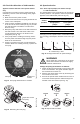
L3
L1
L2
P1
P2
T5
T4 T6
T3 T2 T1
Jumper wire
TM03 7739 4806
L1
L2
L3
P1
P2
T6
T4
T5
T1
T2
T3