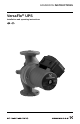
GRUNDFOS INSTRUCTIONS VersaFlo® UPS Installation and operating instructions
LIMITED WARRANTY Products manufactured by GRUNDFOS PUMPS CORPORATION (Grundfos) are warranted to the original user only to be free of defects in material and workmanship for a period of 24 months from date of installation, but not more than 30 months from date of manufacture. Grundfos' liability under this warranty shall be limited to repairing or replacing at Grundfos' option, without charge, F.O.B. Grundfos' factory or authorized service station, any product of Grundfos' manufacture.
VersaFlo® UPS Installation and operating instructions Notice d’installation et d’entretien 4 20 3
CONTENTS 1. 1.1 1.2 2. 2.1 2.2 2.3 2.4 3. 3.1 3.2 3.3 3.4 4. 4.1 4.2 4.3 5. 5.1 5.2 5.3 5.4 5.5 5.6 6. 6.1 6.2 6.3 7.
2.4 Pumped liquid requirements CAUTION: The VersaFlo UPS pump is intended for use with water only. The pump can be used to circulate: • Potable hot water • Water for hydronic heating • Cooling water • In domestic hot-water systems it is advisable to use bronze pumps (VersaFlo UPS model) only for water with a degree of hardness lower than 14 grains per gallon of hardness. For water with a higher degree of hardness, a direct-coupled VersaFlo TP pump is recommended.
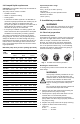
5. Check to make sure the rotor turns freely. Do this by removing the vent plug in the middle of the pump nameplate. Insert a medium size flat-blade screwdriver into the slot at the exposed end of the shaft. Gently turn the shaft. If it does not turn easily, repeat steps 1 to 4 above. 6. The position of the nameplate can be changed by easing the outer edge of the plate at the cutout with a screwdriver. Turn the nameplate to the required position and push into place. 7.
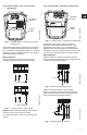
3.4.1 VersaFlo UPS 1 x 115 V and 1 x 230 V terminal box 3.4.2 VersaFlo UPS 3 x 208-230 V terminal box All VersaFlo UPS single-phase pumps come with a protection module and a speed switch as shown in fig. 3. All pumps are equipped with built-in, automatic resetting, thermal overload protection. The pump is protected at all three speeds. Wiring diagrams Figure 4 shows the electrical connections for a single-phase pump with protection module. Fig.
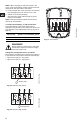
3.4.3 VersaFlo UPS 3 x 460 V and 575 V terminal box Figure 10 shows the electrical connections when using external impulse contacts (momentary contacts) for start/stop push button station. L1 L2 T3 T4 T2 T6 T1 K TM03 7739 4806 T5 L3 Jumpers L1 L2 Fig. 8 VersaFlo UPS 3 x 460 V and 575 V terminal box Wiring diagrams Figure 9 shows the electrical connections when using an external changeover contact (safety circuit) for start/stop push button station.
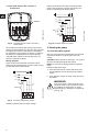
4.2 Check the direction of shaft rotation 4.3 Speed selection Applies to 460 V and 575 V two-speed models only (The direction of rotation of three-speed pumps is checked by means of the fault finding chart, pages 11 and 12). 1. Make sure that the power is OFF. 2. Unscrew and remove the vent plug located at the center of the nameplate. 3. Insert a small, flat-blade screwdriver into the slot in the end of the motor shaft (see fig. 12). Rotate the shaft with the screwdriver to make sure it does so freely. 4.
NOTE: When changing to and from speed 1, the cover of the speed switch module must be removed and fitted on the other side of the switch. 4. Fit the terminal box cover back onto the terminal box and tighten the four screws in the cover. 5. Switch on the electrical supply. Check that the green indicator light is permanently on or flashing. NOTE: The speed switch module must never be used as an on/off switch. L3 P2 P1 T5 T3 Speed step Speed in % of maximum speed 1 approx. 75% 2 100% Fig.
5. Troubleshooting 5.1 Fault finding chart WARNING! Before removing the terminal box cover, make sure that the electrical supply has been switched off and that it cannot be accidentally switched on. The pumped liquid may be scalding hot and under high pressure. Before any removal or dismantling of the pump, the system must be drained or the isolation valves on both sides of the pump must be closed. Fault Cause Remedy 1. The pump does not run. None of the indicator lights are on.
Fault Cause Remedy 7. Single-phase pumps with protection module (only). The pump does not run. The red indicator light is on. The green indicator light is off. a) The pump has been cut out by the thermal overload switch due to high liquid temperature or blocked rotor. Check that the liquid temperature falls within the specified range. The pump will restart automatically when it has cooled to normal temperature.
5.4 Insulation resistance (lead-to-ground) To To 1. 2. 3. To check the insulation resistance (lead-to-ground) of the motor and leads, a megohmmeter is required. To do so, follow these steps: 1. Turn the POWER OFF. 2. Disconnect all electrical leads to the motor. 3. Set the scale selector on the megohmmeter to R x 100K, touch its leads together, and adjust the indicator to zero. 4. Touch the leads of the megohmmeter individually to each of the motor leads and to ground (i.e.
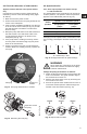
5.5 Winding resistance (line-to-line) To check the winding resistance of the motor windings, a megohmmeter is required. To do so, follow these steps: 1. Turn the POWER OFF. 2. Disconnect all electrical leads to the motor. 3. Set the scale selector on the megohmmeter to R x 1, touch its leads together, and adjust the indicator to zero. 4. Using the charts below for reference, touch the leads of the megohmmeter to the appropriate pair of connectors.
Internal wiring UPS Terminal plug in stator Three-phase 460/575 V 1 3 5 13 7 9 11 15 15
5.6 Winding resistance chart 60 Hz [Ω] 68ºF - 122ºF (20ºC - 50ºC) Pump type RA RS1 RS2 17.8 - 23.2 3.95 - 5.20 9.40 - 12.4 70.0 - 91.5 17.0 - 22.2 39.5 - 52.0 1 x 115 V 9.55 - 12.6 3.05 - 4.00 6.70 - 8.80 1 x 230 V 19.4 - 25.5 5.45 - 7.10 12.6 - 16.4 1 x 115 V 4.15 - 5.45 1.20 - 1.56 2.65 - 3.50 1 x 230 V 8.30 - 10.8 2.20 - 2.90 5.05 - 6.
[Ω] 68ºF - 122ºF (20ºC - 50ºC) Pump type UPS 50-40/4 UPS 50-80/2 UPS 50-80/4 Voltage RA RS1 RS2 1 x 115 V 6.55 - 8.55 2.12 - 2.80 4.30 - 5.65 1 x 230 V 25.0 - 33.0 8.30 - 10.8 15.0 - 19.8 1 x 115 V 4.15 - 5.45 1.20 - 1.56 2.65 - 3.50 1 x 230 V 8.30 - 10.80 2.20 - 2.90 5.05 - 6.65 1 x 115 V 2.75 - 3.60 1.74 - 2.30 2.85 - 3.75 1 x 230 V 5.50 - 7.25 2.65 - 3.50 4.95 - 6.50 6.80 - 8.95 2.02 - 2.65 3.70 - 4.85 1 x 115 V 4.15 - 5.45 1.20 - 1.56 2.65 - 3.50 1 x 230 V 8.
6. Replacing components 6.1 Removing the pump head 1. Disconnect or TURN OFF the power supply. 2. Close any isolation valves on either side of the pump to avoid draining the system of liquid. 3. Disconnect the electrical leads from the terminal box. 4. Disconnect and remove the conduit from the terminal box. 5. Loosen and remove the four allen-head screws (8 or 10 mm) which connect the pump head housing to the pump housing. 6. Remove the pump head from the pump housing. 7.
6.3 Replacing the terminal box or capacitor If the terminal box is replaced, make certain the electrical information listed on the new box matches the information listed on the old box, and that it is compatible with the pump and incoming electrical supply. For all terminal boxes, it is very important to tightly secure the frame grounding screw through the terminal box, so that a proper connection between the terminal box and motor is made.
GARANTIE LIMITÉE Les produits fabriqués par GRUNDFOS PUMPS CORPORATION (Grundfos) sont couverts par une garantie à l'utilisateur initial à l'effet qu'ils sont exempts de vices attribuables aux matériaux et à la fabrication pour une période de 24 mois après la date d'installation, mais sans excéder une période de 30 mois après la date de fabrication.
SOMMAIRE 1. 1.1 1.2 2. 2.1 2.2 2.3 2.4 3. 3.1 3.2 3.3 3.4 4. 4.1 4.2 4.3 5. 5.1 5.2 5.3 5.4 5.5 5.6 6. 6.1 6.2 6.3 7.
2.4 Conditions ayant trait au liquide pompé ATTENTION : La pompe VersaFlo UPS est destinée à pomper uniquement de l'eau. Il peut s'agir d'eau • chaude et potable • pour système de chauffage à eau chaude • de refroidissement • Il est recommandé d'utiliser des pompes en bronze (modèle VersaFlo UPS) dans les systèmes d'eau domestique où la dureté de l'eau est inférieure à 14 grains par gallon impérial. Pour de l'eau avec une dureté supérieure, une pompe à moteur ventilé type TP est recommandée.
4. Serrez les vis creuses au couple suivant, de façon égale : 8 mm : 15 pi/lb 10 mm : 25 pi/lb. 5. Vérifiez que le rotor peut tourner librement en retirant le bouchon d'aération situé au milieu de la plaque signalétique de la pompe. Insérez un tournevis moyen à tête plate dans la fente à l'extrémité exposée de l'arbre, et tournez-le doucement. Si l'arbre ne tourne pas facilement, répétez les étapes 1 à 4 ci-dessus. 6.
3.4.1 Boîtier de raccordement de la pompe VersaFlo UPS 1 x 115 V et 230 V NOTA : On doit installer un disjoncteur électrique et un dispositif de protection contre les surintensités de courant conformément aux codes électriques locaux. K = Contacteur extérieur dont la capacité est compatible avec l'intensité de courant des pompes FL et LR. 3.4.2 Boîtier de raccordement de la pompe VersaFlo UPS 3 x 208-230 V Fig.
La figure 7 montre les connexions électriques applicables lorsqu'on utilise des contacts d'impulsion extérieurs (contacts momentanés) au poste de commande à boutons-poussoirs d'arrêt/marche. L1 L2 L3 L3 L2 L1 K K L3 L2 L1 Fig. 7 L3 T5 T3 L1 L2 T4 T2 T6 L3 P1 T3 L2 T2 L1 T1 P2 Fig. 9 Contacts d'impulsion extérieurs Contact de basculement extérieur Contacts auxiliaires dont la capacité est compatible avec la source d'alimentation électrique.
AVERTISSEMENT ! Vis d'inspection/ 4.2 Vérifier le sens de rotation de l'arbre Inspection screw bouchon d'aération Fig. 12 Retirant le bouchon d'aération 4.3 Sélection de la vitesse 4.3.1 Pompes à trois vitesses, tous les modèles, sauf les modèles 3 x 460 V et 575 V On peut tourner le commutateur de vitesse dans le boîtier de raccordement pour le sélectionner une des 3 (trois) vitesses.
Modifiez le rendement de la pompe comme suit : La vitesse est modifiée par la position des cavaliers dans les bornes. Les cavaliers sont placés comme suit : • figure 15 pour la vitesse 1 – vitesse lente • figure 16 pour la vitesse 2 – vitesse rapide. VITESSE 2 3 1 environ 75% 2 100% T1 T4 T6 P1 P2 L3 L2 L1 T3 T2 T1 T4 T5 T6 Cavalier Fig. 16 Vitesse 2 (pour la vitesse rapide) L3 P2 P1 T5 T3 L1 L2 T4 T2 T6 T1 TM03 7739 4806 4.3.
5. Résolution des problèmes 5.1 Tableau de recherche de défauts AVERTISSEMENT ! Avant de retirer le couvercle du boîtier de raccordement, assurez-vous que l'alimentation électrique a été coupée, et qu'il n'y a aucun risque que l'alimentation soit rétablie par accident. Le liquide pompé peut être brûlant et sous haute pression. Avant tout retrait ou démontage de la pompe, le système doit être purgé ou les deux vannes d'isolation, de chaque coté de la pompe, doivent être fermées.
Problème Cause Solution 7. Pompes avec moa) La pompe a été mise hors dule de protection circuit par le commutateur seulement : de surcharge thermique, La pompe ne foncceci est causé par la tionne pas. température élevée du L'indicateur lumineux liquide, ou le rotor est rouge est allumé. bloqué. L'indicateur lumineux vert est éteint. Assurez-vous que la température du liquide est conforme à la plage spécifiée.
Utilisez un ampèremètre pour vérifier le courant. Pour le faire, suivez les étapes suivantes : 1. Assurez-vous que la pompe fonctionne. 2. Réglez l'ampèremètre à l'échelle appropriée. 3. Placez les pincettes de l'ampèremètre sur les conducteurs que vous voulez mesurer. 4. Comparez les résultats avec les données d'intensité de courant indiquées sur la plaque signalétique. 5. Répétez la procédure pour les autres conducteurs.
5.5 Résistance d'enroulement (phase à phase) Utilisez un mégohmmètre pour vérifier la résistance des enroulements du moteur. Pour le faire, suivez les étapes suivantes : 1. COUPEZ l'alimentation électrique. 2. Déconnectez tous les fils électriques du moteur. 3. Réglez le sélecteur d'échelle du mégohmmètre à R x 1, connectez les sondes ensemble, et réglez l'indicateur à zéro. 4. En utilisant les tableaux ci-dessous comme référence, connectez les sondes du mégohmmètre à la paire appropriée de conducteurs.
Câblage interne UPS Fiche de raccordement du stator Triphasé 460/575 V 32 1 3 5 13 7 9 11 15
5.
[Ω] 68ºF - 122ºF (20ºC - 50ºC) Modèle de la pompe RA RS1 RS2 4,15 - 5,45 1,20 - 1,56 2,65 - 3,50 8,30 - 10,80 2,20 - 2,90 5,05 - 6,65 1 x 115 V 2,75 - 3,60 1,74 - 2,30 2,85 - 3,75 1 x 230 V 5,50 - 7,25 2,65 - 3,50 4,95 - 6,50 6,80 - 8,95 2,02 - 2,65 3,70 - 4,85 1 x 115 V 4,15 - 5,45 1,20 - 1,56 2,65 - 3,50 1 x 230 V 8,30 - 10,80 2,20 - 2,90 5,05 - 6,65 6,80 - 8,95 2,02 - 2,65 3,70 - 4,85 Tension R 1 x 115 V 1 x 230 V UPS 50-80/2 UPS 50-80/4 3 x 208 - 230 V 26,0 - 34,0 3
6. Remplacement de composantes 6.1 Démontage de la tête de pompe 1. Débranchez ou COUPEZ l'alimentation électrique. 2. Fermez les vannes d'isolation situées de chaque côté de la pompe pour éviter de drainer le liquide du système. 3. Déconnectez tous les fils électriques du boîtier de raccordement. 4. Déconnectez et enlevez le conduit du boîtier de raccordement. 5. Desserrez et enlevez les quatre vis creuses (8 ou 10 mm) qui retiennent le boîtier de la tête de pompe au corps de pompe. 6.
6.3 Remplacer le boîtier de raccordement ou le condensateur Si le boîtier de raccordement est remplacé, assurezvous que les données électriques indiquées sur le nouveau boîtier correspondent aux données indiquées sur l'ancien boîtier, et qu'il est compatible avec la pompe et la source d'alimentation électrique.
U.S.A. Canada México GRUNDFOS Pumps Corporation 17100 West 118th Terrace Olathe, Kansas 66061 Phone: +1-913-227-3400 Telefax: +1-913-227-3500 GRUNDFOS Canada Inc. 2941 Brighton Road Oakville, Ontario L6H 6C9 Phone: +1-905 829 9533 Telefax: +1-905 829 9512 Bombas GRUNDFOS de México S.A. de C.V. Boulevard TLC No. 15 Parque Industrial Stiva Aeropuerto Apodaca, N.L.C.P. 66600 Phone: +52-81-8144 4000 Telefax: +52-81-8144 4010 Addresses revised 22.09.
Being responsible is our foundation Thinking ahead makes it possible Innovation is the essence L-UPS-TL-01 96459998 0207 (DK#96459998) 02/07 (US) 243 Repl. 96459998 Subject to 0303 alterations www.grundfos.