
Brochure
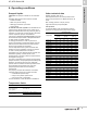

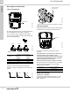
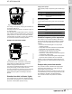
Table Of Contents
- 1. Product introduction
- 2. Product overview
- 3. Product range
- 4. Cross-reference guide
- 5. Construction
- 6. Operating conditions
- 7. Functions
- 8. Technical data
- 9. Curve charts and technical data
- UPS 32-40/4, 1 ph, 115 V, 230 V, 60 Hz
- UPS 32-40/4, 3 ph, 208-230 V, 460 V, 575 V«, 60 Hz
- UPS 32-80/2, 1 ph, 115 V, 230 V, 60 Hz
- UPS 32-80/2, 3 ph, 208-230 V, 460 V, 575 V«, 60 Hz
- UPS 32-160/2, 1 ph, 115 V, 230 V, 60 Hz
- UPS 32-160/2, 3 ph, 208-230 V, 460 V, 575 V«, 60 Hz
- UPS 40-40/4, 1 ph, 115 V, 230 V, 60 Hz
- UPS 40-40/4, 3 ph, 208-230 V, 460 V, 575 V«, 60 Hz
- UPS 40-80/4, 1 ph, 115 V, 230 V, 60 Hz
- UPS 40-80/4, 3 ph, 208-230 V, 460 V, 575 V«, 60 Hz
- UPS 40-80/2, 1 ph, 115 V, 230 V, 60 Hz
- UPS 40-80/2, 3 ph, 208-230 V, 460 V, 575 V«, 60 Hz
- UPS 40-160/2, 1 ph, 115 V, 230 V, 60 Hz
- UPS 40-160/2, 3 ph, 208-230 V, 460 V, 575 V«, 60 Hz
- UPS 40-240/2, 1 ph, 230 V, 60 Hz
- UPS 40-240/2, 3 ph, 208-230 V, 460 V, 575 V«, 60 Hz
- UPS 50-40/4, 1 ph, 115 V, 230 V, 60 Hz
- UPS 50-40/4, 3 ph, 208-230 V, 460 V, 575 V«, 60 Hz
- UPS 50-80/4, 1 ph, 115 V, 230 V, 60 Hz
- UPS 50-80/4, 3 ph, 208-230 V, 460 V, 575 V«, 60 Hz
- UPS 50-80/2, 1 ph, 115 V, 230 V, 60 Hz
- UPS 50-80/2, 3 ph, 208-230 V, 460 V, 575 V«, 60 Hz
- UPS 50-160/2, 1 ph, 230 V, 60 Hz
- UPS 50-160/2, 3 ph, 208-230 V, 460 V, 575 V«, 60 Hz
- UPS 50-240/2, 3 ph, 208-230 V, 460 V, 575 V«, 60 Hz
- UPS 53-55/57, 1 ph, 115 V, 230 V, 60 Hz
- UPS 53-55/57, 3 ph, 208-230 V, 460 V, 575 V«, 60 Hz
- UPS 75-69/2, 1 ph, 230 V, 60 Hz
- UPS 75-69/2, 3 ph, 208-230 V, 460 V, 575 V«, 60 Hz
- UPS 80-40/4, 3 ph, 208-230 V, 460 V, 575 V«, 60 Hz
- UPS 80-80/4, 3 ph, 208-230 V, 60 Hz
- UPS 80-160/2, 3 ph, 208-230 V, 460 V, 575 V«, 60 Hz
- UPS 100-40/4, 3 ph, 208-230 V, 460 V, 575 V«, 60 Hz
- UP 43-70, 1 ph, 115 V / 230 V, 60 Hz
- UP 43/110, 1 ph, 115 V / 230 V, 60 Hz
- UP 53-45, 1 ph, 115 V / 230 V, 60 Hz
- UP 53-46, 1 ph, 115 V / 230 V, 60 Hz
- 10. Accessories and spare parts
- 11. Further documentation

Construction
UP, UPS Series 200
5
12
Motor
The motor, pos. 4, is a 2- or 4-pole, asynchronous
squirrel-cage motor. As the motor is cooled by the
pumped liquid, the noise level is very low.
Stator housing
Pressure die-cast aluminum stator housing can be
turned to change the position of the terminal box.
The stator housing has eight drain holes to enable
condensed water to escape. The vent hole under the
terminal box allows the water to evaporate from the
stator. The drain holes must point downwards.
The permissible terminal box positions are shown in
the drawing below. The positions apply to both vertical
and horizontal mounting.
Fig. 4 Possible terminal box positions
Note: The terminal box must only be turned to the
above positions.
The drawing below shows the standard box position.
Fig. 5 Standard terminal box position
The nameplate can be turned in steps of 45°.
The positions of the terminal box and the nameplate
are changed as described above.
The stator wires are self-bonding. The wires and the
terminal box are connected by a terminal plug.
The stator incorporates a thermal overload switch for
protection of the motor if the winding temperature
becomes too high.
Rotor can
The rotor can (pos. 7) is made of drawn steel sheet
and fitted with an inspection screw directly at the top.
There is an O-ring seal between the inspection screw
and the rotor can. For reasons of safety, the hole for
the inspection screw will deflect a possible jet of liquid
if the inspection screw is removed.
The outer radial bearing is fitted into the top of the
rotor can.
Shaft with rotor
The shaft (pos. 8) is made of stainless steel and
equipped with two tungsten carbide bearings.
To further improve the internal circulation of the
pumped liquid in the rotor can, the shaft of 4-pole
motors is fitted with a small rotor impeller.
The rotor is made of soft-annealed iron lamination and
provided with copper or brass bars. The short-circuit
rings are made of copper.
The rotor is encapsulated in a thin stainless steel
cladding and dynamically balanced.
The thrust bearing is secured to the shaft in a
spherically flexible suspension.
Bearing plate
The bearing plate (pos. 10) is made of stainless steel.
The inner radial bearing is pressed into the bearing
plate, ground and honed. The relatively large bearing
plate surface means that motor heat is effectively
carried away by the pumped liquid.
Impeller
The stainless steel impeller (pos. 13) is of the radial
type with curved blades. It is secured to the shaft by a
split cone and nut (left-hand thread).
Pump housing
The pump housing (pos. 16) is available in cast iron or
bronze. All pump housings are flanged for the
individual markets.
See also section 4. Cross-reference guide on page 8
and section 5. Construction on page 10 concerning
flanges and port-to-port lengths.
The pump housing is of the in-line type. A stainless
steel/PTFE neck ring minimizes the recirculation and
improves pump efficiency.
The bottom of the housing has threaded holes for
fastening to a baseplate.
TM02 1398 1101TM03 2260 4005