
Install Instructions

8
(QJOLVK86
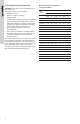
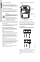
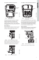
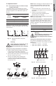
Figure 10 shows the electrical connections when
using external impulse contacts (momentary
contacts) for start/stop push button station.
Fig. 10 External impulse contacts
5. Starting the pump
5.1 Vent the piping system
After the pump has been installed and the
electrical connections made, the piping system
must be vented.
CAUTION: Never operate the pump dry — the
system must first be filled with liquid and vented.
NOTE: Do not vent the piping system through
the pump.
Instead, follow these steps:
1. Fill and pressurize the system with liquid,
and vent all trapped air from the piping by
suitable means.
2. If any isolation valves are used, make sure
they are OPEN.
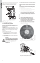
5.2 Check the direction of shaft rotation
Applies to 460 V and 575 V two-speed models
only
(The direction of rotation of three-speed pumps
is checked by means of the fault finding chart,
p. 10 and p. 11).
1. Make sure that the power is OFF.
2. Unscrew and remove the vent plug located
at the center of the nameplate.
3. Insert a small, flat-blade screwdriver into the
slot in the end of the motor shaft (see fig.
12). Rotate the shaft with the screwdriver to
make sure it does so freely.
4. Bump the pump and watch to see which
direction the shaft rotates. The shaft must
rotate in the counterclockwise direction as
shown on the nameplate (see fig. 11).
5. If the pump shaft is rotating incorrectly,
disconnect the power and interchange any
two power leads in the terminal box.
6. Check once again for proper counterclock-
wise rotation. When it is rotating correctly,
replace the vent plug.
Fig. 11 Vent plug and direction of rotation
Fig. 12 Removing the vent plug
TM03 7737 4806
Warning
If the vent screw is to be loosened,
care should be taken to ensure that
the escaping scalding hot liquid
does not cause personal injury
or damage to components
(see fig. 12).
L3
L1
L2
K
K
L3
L2
L1
Start
K
Stop
P1
P2
T3 T2
T1
TM03 7750 4806
TM03 7277 4706
Vent plug
Direction of
rotation
Inspection scre
Inspection
screw/
vent plug