
Install Instructions

18
(QJOLVK86
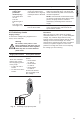
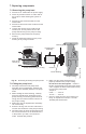
7.3 Replacing the terminal box or
capacitor
If the terminal box is replaced, make certain the
electrical information listed on the new box
matches the information listed on the old box,
and that it is compatible with the pump and
incoming electrical supply.
For all terminal boxes, it is very important to
tightly secure the frame grounding screw
through the
terminal box, so that a proper connection
between the terminal box and motor is made.
Fig. 21 Terminal box
8. Disposal
This product or parts of it must be disposed of in
an environmentally sound way:
1. Use the public or private waste collection
service.
2. If this is not possible, contact the nearest
Grundfos company or service workshop.
TM03 7742 4806
Frame ground
screw hole
Standard
module
Speed
switch
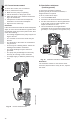
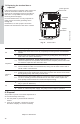
Electrical information
All
1. Before replacing the terminal box or capacitor, make sure the power is OFF.
2.
Remove the terminal box cover by completely loosening all four torx/standard
screws.
3.
Remove the speed switch (noting its position) by pulling firmly and evenly on
both sides of it. (Not for 460/575 V).
Capacitor
a.4.
Capacitor replacement, single-phase pumps only: Disconnect the two
connector clips from the capacitor and unscrew the complete plastic strain relief
nut. Remove capacitor wire and strain relief.
a.5.
Screw in new complete strain relief nut and connect new clip connectors. Pull
excess sheathed cable out of terminal box, being sure to leave at least 1/8" of
sheath inside of terminal box.
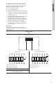
Terminal
box
b.4.
Terminal box replacement: Disconnect all wiring, remove the three
phillips-head screws holding the terminal box in place and remove the terminal
box by pulling firmly and evenly on both sides.
b.5.
Check that the clear rubber gasket is in place around the terminal box connec-
tor stem, carefully press the terminal box into the stator socket, replace the
three phillips-head terminal box screws and replace wiring.
All
6.
Replace the speed switch to its proper position, making sure to push it all the
way in. (Not for 460/575 V).
7. Replace the terminal box cover and tighten all four torx/standard screws.
8. Switch on electrical power supply. The pump is now ready for operation.
Subject to alterations.