
Install Instructions

11
(QJOLVK86
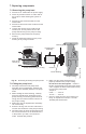
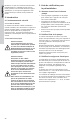
6.2 Preliminary checks
Supply voltage
To check the voltage being supplied to the
motor, use a voltmeter.
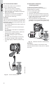
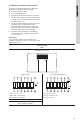
Fig. 17 Checking single-phase power
Evaluation
When the motor is under load, the voltage
should be within 10 % (+ or –) of the nameplate
voltage. Any variation larger than this may
indicate a poor electrical supply and can cause
damage to the motor windings. The motor
should not be operated under these conditions.
Contact your power supplier to correct the
problem or change the motor to one requiring
the voltage you are receiving.
7. Single-phase
pumps with
protection
module (only).
The pump does
not run.
The red
indicator light is
on.
The green indi-
cator light is off.
a) The pump has been cut
out by the thermal over-
load switch due to high liq-
uid temperature or blocked
rotor.
Check that the liquid temperature falls
within the specified range. The pump will
restart automatically when it has cooled to
normal temperature.
NOTE: If the thermal overload switch has
cut out the pump three times within a short
period, the pump must be restarted
manually by switching off the electrical
supply.
b) The speed switch module
has not been fitted.
Switch off the electrical supply by means
of the external mains switch and fit the
speed switch module.
Fault Cause Remedy
Warning
Be careful, since power is still
being supplied to the pump. Do not
touch the voltmeter leads together
while they are in contact with the
power lines.
Single-phase motors Three-phase motors
Touch one voltmeter
lead to each of the
lines supplying power
to the pump:
• L and N for 115 V
circuits
• L1 and L2 for 230 V
circuits.
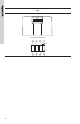
Touch a voltmeter
lead to:
• Power leads
L1 and L2
• Power leads
L2 and L3
• Power leads
L3 and L1.
These tests should
give a reading of full
line voltage.
TM03 7749 4806
L
1
L
2