
Brochure
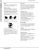
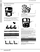
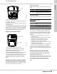
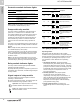
Table Of Contents
- 1. Product introduction
- 2. Product overview
- 3. Product range
- 4. Cross-reference guide
- 5. Construction
- 6. Operating conditions
- 7. Functions
- 8. Technical data
- 9. Curve charts and technical data
- UPS 32-40/4, 1 ph, 115 V, 230 V, 60 Hz
- UPS 32-40/4, 3 ph, 208-230 V, 460 V, 575 V«, 60 Hz
- UPS 32-80/2, 1 ph, 115 V, 230 V, 60 Hz
- UPS 32-80/2, 3 ph, 208-230 V, 460 V, 575 V«, 60 Hz
- UPS 32-160/2, 1 ph, 115 V, 230 V, 60 Hz
- UPS 32-160/2, 3 ph, 208-230 V, 460 V, 575 V«, 60 Hz
- UPS 40-40/4, 1 ph, 115 V, 230 V, 60 Hz
- UPS 40-40/4, 3 ph, 208-230 V, 460 V, 575 V«, 60 Hz
- UPS 40-80/4, 1 ph, 115 V, 230 V, 60 Hz
- UPS 40-80/4, 3 ph, 208-230 V, 460 V, 575 V«, 60 Hz
- UPS 40-80/2, 1 ph, 115 V, 230 V, 60 Hz
- UPS 40-80/2, 3 ph, 208-230 V, 460 V, 575 V«, 60 Hz
- UPS 40-160/2, 1 ph, 115 V, 230 V, 60 Hz
- UPS 40-160/2, 3 ph, 208-230 V, 460 V, 575 V«, 60 Hz
- UPS 40-240/2, 1 ph, 230 V, 60 Hz
- UPS 40-240/2, 3 ph, 208-230 V, 460 V, 575 V«, 60 Hz
- UPS 50-40/4, 1 ph, 115 V, 230 V, 60 Hz
- UPS 50-40/4, 3 ph, 208-230 V, 460 V, 575 V«, 60 Hz
- UPS 50-80/4, 1 ph, 115 V, 230 V, 60 Hz
- UPS 50-80/4, 3 ph, 208-230 V, 460 V, 575 V«, 60 Hz
- UPS 50-80/2, 1 ph, 115 V, 230 V, 60 Hz
- UPS 50-80/2, 3 ph, 208-230 V, 460 V, 575 V«, 60 Hz
- UPS 50-160/2, 1 ph, 230 V, 60 Hz
- UPS 50-160/2, 3 ph, 208-230 V, 460 V, 575 V«, 60 Hz
- UPS 50-240/2, 3 ph, 208-230 V, 460 V, 575 V«, 60 Hz
- UPS 53-55/57, 1 ph, 115 V, 230 V, 60 Hz
- UPS 53-55/57, 3 ph, 208-230 V, 460 V, 575 V«, 60 Hz
- UPS 75-69/2, 1 ph, 230 V, 60 Hz
- UPS 75-69/2, 3 ph, 208-230 V, 460 V, 575 V«, 60 Hz
- UPS 80-40/4, 3 ph, 208-230 V, 460 V, 575 V«, 60 Hz
- UPS 80-80/4, 3 ph, 208-230 V, 60 Hz
- UPS 80-160/2, 3 ph, 208-230 V, 460 V, 575 V«, 60 Hz
- UPS 100-40/4, 3 ph, 208-230 V, 460 V, 575 V«, 60 Hz
- UP 43-70, 1 ph, 115 V / 230 V, 60 Hz
- UP 43/110, 1 ph, 115 V / 230 V, 60 Hz
- UP 53-45, 1 ph, 115 V / 230 V, 60 Hz
- UP 53-46, 1 ph, 115 V / 230 V, 60 Hz
- 10. Accessories and spare parts
- 11. Further documentation

Functions
UP, UPS Series 200
7
18
Protection module indicator lights
Note: Pumps with protection module must not be
connected to a variable frequency drive.
Pumps with relay module
The relay module is available for UPS pumps as an
option for 1 x 115/230 V and 3 x 208-230 V units.
The module enables direct connection of the pump to
an external power supply switch. Furthermore, the
module has a signal output for external operating or
fault indication. By means of a selector switch the
output can be set to activation during operation or
fault.
The pump is connected directly to the power supply as
the pump incorporates overload protection at all three
speeds.
Note: Pumps with relay module must not be connected
to a variable frequency drive (VFD).
If the pump has been cut out by the thermal overload
switch, it will restart automatically when it has cooled
to normal temperature, provided the external on/off
contact is closed.
Note: If the thermal overload switch has cut out the
pump three times within a short time, the relay must be
reset manually by switching off the electricity supply.
Relay module indicator lights
The relay module indicator lights provides detailed
operating and fault indications.
All pumps with relay module incorporate a green and a
red indicator light. Functions, see table in Signal output
of relay module.
Signal output of relay module
The relay module has a signal output for external
operating or fault indication.
By means of the selector switch, the signal output can
be set to activation during operation or fault.
Operation: The output functions as operating
indication between terminals 2 and 3.
Fault: The output functions as fault indication
between terminals 1 and 3.
Two pumps plumbed in parallel
Operating modes
Both pumps must be fitted with a relay module.
In addition to the signal functions, the signal output of
the relay module for two pumps in parallel can be used
for controlling the operating mode of pump 1 and 2.
It is possible to choose between three operating
modes:
1. Alternating operation. The pumps operate
alternately as duty and standby pump, respectively.
Changeover takes place every 24 hours. If the duty
pump is cut out due to a fault, the standby pump will
automatically start. During changeover both pumps
will be running for a short period to ensure a
low-noise changeover.
2. Standby operation. The pumps operate
continuously as duty and standby pump,
respectively. If the duty pump is cut out due to a
fault, the standby pump will automatically start at a
signal from the output of the duty pump. The
sequence can be changed to make the standby
pump operate as duty pump.
3. Single-pump operation. The pumps run
independently without communicating with each
other.
Indicator lights
Description
Green Red
Off Off
The pump has been stopped. The electricity
supply has been switched off.
On Off The pump is operating.
On On
Three-phase pumps only:
The pump is operating, but the direction of
rotation is wrong.
Off On
The pump has been cut out by the thermal
overload switch.
Indicator lights
Signal output
set to
Description
Green Red
Opera-
tion
Fault
Off Off
The pump has been
stopped. The electricity
supply has been switched
off, or a phase is missing.
On Off The pump is operating.
On On
Only three-phase pumps:
The pump is operating, but
with wrong direction of
rotation.
Off On
The pump has been cut out
by the thermal overload
switch.
Flash-
ing
Off
The pump has been
stopped by an external
on/off switch.
Flash-
ing
On
The pump is or has been
cut out by the thermal
overload switch, and it has
been stopped by an
external on/off switch.
1 32
NC NO C
1 32
NC NO C
1
2 3
NC NO C
1
2 3
NC NO C
1
2 3
NC NO C
1 32
NC NO C
1 32
NC NO C
1 32
NC NO C
1 32
NC NO C
1
2 3
NC NO C
1 32
NC NO C
1 32
NC NO C