
Install Instructions

7
(QJOLVK86
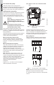
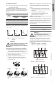
4.4.2 UPS 3 x 208-230 V terminal box
Fig. 5 UPS 3 x 208-230 V
terminal box
All UPS pumps with three-phase x 208-230 V
come with a standard module and a speed
switch as shown in fig. 5. All pumps are
equipped with an internal thermal overload
switch (terminals T1 and T2, to be connected to
an external contactor) to protect the pump at all
three speeds.
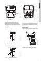
Wiring diagrams
Figure 6 shows the electrical connections when
using an external changeover contact (safety
circuit) for start/stop push button station.
Fig. 6 External changeover contact
Auxiliary contacts rated for supply voltage.
Figure 7 shows the electrical connections when
using external impulse contacts (momentary
contacts) for start/stop push button station.
Fig. 7 External impulse contacts
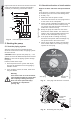
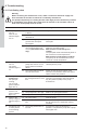
4.4.3 UPS 3 x 460 V and 575 V terminal box
Fig. 8 UPS 3 x 460 V and 575 V
terminal box
All UPS pumps with three-phase x 460 V and
575 V terminal boxes (fig. 8) come with a special
two-speed terminal box. The speed is changed
by the orientation of the jumpers as shown on
p. 9. All pumps are equipped with an internal
thermal overload switch (terminals P1 and P2)
to be connected to external contactor.
Wiring diagrams
Figure 9 shows the electrical connections when
using an external changeover contact (safety
circuit) for start/stop push button station.
Fig. 9 External changeover contact
Auxiliary contacts rated for supply voltage.
TM03 7742 4806
TM03 7892 5106
TM03 7740 4806
Standard
module
Speed
switch
K
K
Stop/Start
L1L2L3T2T1
L1L2L3
K
K
K
Stop
Start
L1L2L3T2T1
L1L2L3
TM03 7739 4806
TM03 7738 5106
L1
L2
L3
P1
P2
T6
T4
T5
T1
T2
T3
Jumpers
K
K
L3
L2
L1
Start/stop
L3
L1
L2
P1
P2
T3 T2 T1