
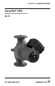
User Guide


4
CONTENTS
Page
1. Safety warning 4
1.1 Read this booklet 4
1.2 Electrical work 4
2. Pre-installation checklist 4
2.1 Confirm you have the correct pump 4
2.2 Check the condition of the pump 4
2.3 Verify electrical requirements 4
2.4 Pumped liquid requirements 5
3. Installation procedures 5
3.1 Electrical preparation 5
3.2 Piping considerations 6
3.3 Connect the pump 6
3.4 Electrical connection 6
4. Starting the pump 8
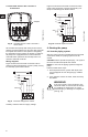
4.1 Vent the piping system 8
4.2 Check the direction of shaft rotation 9
4.3 Speed selection 9
5. Troubleshooting 11
5.1 Fault finding chart 11
5.2 Preliminary checks 12
5.3 Current measurement 13
5.4 Insulation resistance (lead-to-ground) 13
5.5 Winding resistance (line-to-line) 14
5.6 Winding resistance chart 16
6. Replacing components 18
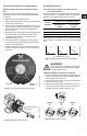
6.1 Removing the pump head 18
6.2 Fitting the pump head 18
6.3 Replacing the terminal box or capacitor 19
7. Disposal 19
1. Safety warning
1.1 Read this booklet
This booklet is designed to help a certified installer
install, begin operation of and troubleshoot the
Grundfos VersaFlo UPS pumps. The booklet should
be left with the owner of the pump for future refer-
ence and information regarding its operation. Should
the owner experience any problems with the pump,
a certified professional should be contacted.
1.2 Electrical work
All electrical work should be performed by a qualified
electrician in accordance with the latest edition of the
National Electrical Code, local codes and regula-
tions.
2. Pre-installation checklist
2.1 Confirm you have the correct pump
• Read the pump nameplate to make sure it is the
one you ordered.
• Compare the pump's nameplate data and its per-
formance curve (for head, GPM, etc.) with the
application in which you plan to install it.
• Will the pump do what you expect it to do?
2.2 Check the condition of the pump
The shipping carton your pump came in is specially
designed around your pump during production to
prevent damage.
As a precaution, it should remain in the carton until
you are ready to install it. At that point, look at the
pump and examine it for any damage that may have
occurred during shipping.
Examine any other parts of the shipment as well for
any visible damage.
2.3 Verify electrical requirements
Verification of the electrical supply should be made
to be certain the voltage, phase and frequency
match that of the pump motor. The proper operating
voltage and other electrical information can be found
on the pump nameplate.
These motors are designed to run on ±10% of the
nameplate-rated voltage.
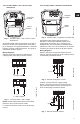
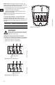
Wiring connection diagrams can be found inside the
terminal box cover and later in these Installation and
Operating Instructions. If voltage variations are
larger than ±10%, do not operate the pump.
WARNING!
A faulty motor or wiring can cause electri-
cal shock that could be fatal, whether
touched directly or conducted through
standing water. For this reason, proper
grounding of the pump to the power sup-
ply's grounding terminal is required for
safe installation and operation.
In all installations, the above-ground metal
plumbing should be connected to the
power supply ground as described in
Article 250-80 of the National Electrical
Code.