
Install Instructions

6
(QJOLVK86
4.3 Connect the pump
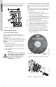
Install the pump into the piping system.
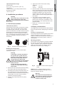
Grundfos recommends that pressure gauges be
installed in the inlet and discharge flanges or
pipes to check pump and system performance.
4.4 Electrical connection
The electrical connection and protection should
be carried out in accordance with the latest
edition of the National Electrical Code, local
codes and regulations by a qualified electrician.
The operating voltage and frequency are
marked on the pump nameplate. Make sure that
the motor is suitable for the electrical supply it is
being installed to.
The pump should be grounded to protect against
indirect contact and a ground fault interrupter
can be used as extra protection.
Multi-speed pump (single-phase)
All single-phase pumps are equipped with
built-in, automatic resetting, thermal overload
protection. The pump is protected at all three
speeds.
Multi-speed pump (three-phase)
The pump must be connected to the electrical
supply via an external contactor. The contactor
must be connected to the built-in thermal
overload switch terminals T1 and T2 (3 x
208-230 V) or P1 and P2 (3 x 460 V and 575 V)
to protect the pump against overloading at all
three speeds.
OR: If the pump is protected by means of a
motor starter, the starter must be set to the
current consumption of the pump at the selected
speed. The motor starter setting must be
changed every time the pump speed is changed.
The current consumption at the individual
speeds is stated on the pump
nameplate.
Figures 4, 6, 7, 9, and 10 on the next pages
show the possible connections.
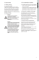
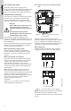
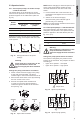
4.4.1 UPS 1 x 115 V and 1 x 230 V terminal
box
Fig. 3 UPS 1 x 115 V and 1 x 230 V
terminal box
All UPS single-phase pumps come with a
protection module and a speed switch as shown
in fig. 3. All pumps are equipped with built-in,
automatic resetting, thermal overload protection.
The pump is protected at all three speeds.
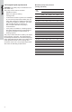
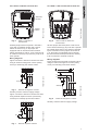
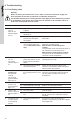
Wiring diagrams
Figure 4 shows the electrical connections for
a single-phase pump with protection module.
Fig. 4 1 x 115 V and 1 x 230 V supply
NOTE: Provide electrical disconnect and current
protection as per local electrical codes.
K = External contactor sized to FL and LR pump
current.
Warning
Never make any connections in the
pump terminal box unless the
electrical supply has been switched
off.
The pump must be grounded.
The pump must be connected to an
external main power switch.
TM03 7744 4806TM03 7743 4806
Protection
module
Speed
switch
L1 L2
1 x 115 V supply
1 x 230 V supply