
Submittal Sheet
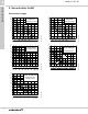
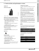
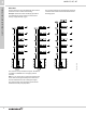
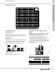
Table Of Contents
- 1. Product overview, Unilift
- 2. General data, Unilift
- 3. Technical data and performance curves
- 4. Control panels
- 5. Alarms
- 6. Accessories
- 7. Pump and system sizing instructions
- 8. Grundfos Product Center

Technical data and performance curves
Unilift CC, KP, AP
3
7
3. Technical data and performance curves
Unilift CC
Product description
Fig. 1 Unilift CC
Unilift CC 5, CC 7 and CC 9 pumps are single-stage
submersible pumps able to pump down to 0.12" water
level. The pumps are designed for pumping rainwater
and grey wastewater from places such as
• washing machines, baths, sinks, etc. from low-lying
parts of buildings up to sewer level
• cellars or buildings prone to flooding
• draining wells
• collecting wells for surface water with inlets from
roof gutters, tunnels, etc.
• swimming pools, ponds or fountains.
The pumps are suitable for permanent installation or
they can be used as portable pumps. They are
available in two versions:
• M for manual operation
• A for automatic operation.
The pumps allow free passage of particles up to 0.4".
Approvals
Pumped liquids
The pumps are suitable for these liquids:
• clean, non-aggressive water
• slightly dirty (grey) wastewater.
The pumps are not suitable for these liquids:
• liquids containing long fibres
• inflammable liquids (oil, petrol, etc.)
• aggressive liquids.
If the pump has been used for other liquids than clean
water, it should be flushed through with clean water
immediately after use.
Components included
The pump is supplied with an adapter and a non-return
valve.
The adapter has 0.75", 1" and 1.25" NPT external
threads. It must be cut to fit the discharge pipe.
The non-return valve can be fitted in the adapter to
pre-vent backflow through the pump when it stops.
Pump sleeve and housing
The sleeve is made of composite material cast in one
piece with a 1.25" NPT external pipe thread (G)
discharge connection. A slot on the handle holds the
float switch cable.
The main cable and flow switch cable are introduced
into the sleeve through hermetically sealed cable
entries.
The suction strainer is fitted to the sleeve by giving it a
light push and can be removed easily by means of a
screwdriver or similar tool. The water enters the pump
through the holes of the suction strainer preventing the
passage of large solids. The large holes also ensure a
slow flow into the pump.
Suction to low water level is obtained by removing the
strainer.
Motor
The motor is a single-phase, asynchronous, dry-rotor
motor. The axial rotor position is secured by means of
a ball bearing. The motor is cooled by the pumped
liquid around the motor.
The motor incorporates automatic overload protection
cutting out the motor in case of overload. When cooled
to normal temperature, the motor will restart
automatically.
Materials
TM03 1358 1805
US
C
Insulation class Enclosure class
Unilift CC 5 B (115 V) F (230 V) IP68
Unilift CC 7 B (115 V) F (230 V) IP68
Unilift CC 9 B IP68
Component Material DIN W.-Nr.
Motor sleeve PP 15 GF
Pump sleeve PP 15 GF
Impeller PPOm 20 GF
Suction strainer Stainless steel class A2 1.4301
V-ring NBR 50
O-rings NBR 70
Cable SJTW-A 3AWG18