GRUNDFOS DATA BOOKLET Unilift CC, KP, AP Submersible wastewater pumps 60 Hz
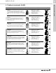
Unilift CC, KP, AP Table of contents 1. 2. 3. 4. 5. 6. 7. 8.
Unilift CC, KP, AP 1 • • • • • Max. flow rate, Q: 79 GPM Max. head, H: 39 feet Liquid temp.: 32 °F to 131 °F Max. particle size: 1.4" Material: Stainless steel. • • • • • Max. flow rate, Q: 92 GPM Max. head, H: 43 feet Liquid temp.: 32 °F to 104 °F Max. particle size: 1.4" Material: Stainless steel • • • • • Max. flow rate, Q: 140 GPM Max. head, H: 41 feet Liquid temp.: 32 °F to 131 °F Max. particle size: 2.0" Material: Stainless steel. • • • • • Max. flow rate, Q: 136 GPM Max.
Unilift CC, KP, AP 2 General data, Unilift 2.
Unilift CC, KP, AP 2 The Unilift CC, KP and AP are submersible wastewater pumps suitable for temporary as well as permanent free-standing installation. The pumps are designed for intermittent operation. General data, Unilift Applications pH values: • Unilift CC: 4 to 9 • Unilift KP: 4 to 9 • Unilift AP: 4 to 10. Maximum density: 146.88 ounce/gallon. Maximum installation depth below water level: 34 feet. Examples of applications Unilift pump type Application CC KP AP12 AP35 AP35B AP50 AP50B Max.
Unilift CC, KP, AP 2 General data, Unilift Type keys Construction Unilift CC pumps Vertical, single-stage, submersible centrifugal pumps with horizontal or vertical discharge port designed for free-standing installation or for installation in collecting tanks. The pumps are directly connected to an asynchronous submersible motor for 1 x 115 V + 6/- 10 %, 1 x 230 V + 6/- 10 %, 60 Hz. Enclosure class: IP68 Insulation class: B or F.
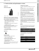
Unilift CC, KP, AP 3 Unilift CC Technical data and performance curves 3. Technical data and performance curves Components included The pump is supplied with an adapter and a non-return valve. The adapter has 0.75", 1" and 1.25" NPT external threads. It must be cut to fit the discharge pipe. The non-return valve can be fitted in the adapter to pre-vent backflow through the pump when it stops. Product description TM03 1358 1805 Pump sleeve and housing Fig.
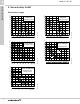
Unilift CC, KP, AP 3 Technical data and performance curves Selection The overview below shows the maximum lengths of combined vertical and horizontal Schedule 40 PVC discharge pipes. TM04 3041 3508 The flow velocity through the discharge pipe must be minimum 2.3 ft/s to ensure self-cleaning. Example: Schedule 40 PVC discharge pipe with an inner diameter of 0.824" requires a minimum flow velocity of approximately 4 gpm. The overview is only intended as a guide.
Unilift CC, KP, AP 3 Technical data and performance curves Performance curves H [ft] Unilift CC 32 60 Hz -9 30 28 26 -7 24 22 20 18 -5 16 14 12 10 8 6 TM04 2257 2208 4 2 0 0 0 5 10 2 15 20 4 25 30 6 35 8 40 45 50 10 55 60 Q [US GPM] 12 14 Q [m³/h] Adjustment of cable length for float switch Operating conditions Liquid temperature 32 °F to 104 °F. However, at intervals of at least 30 minutes, the pump is allowed to run at maximum +158 °F for periods not exceeding two minutes.
Unilift CC, KP, AP 3 Technical data and performance curves Technical data Product no.
Unilift CC, KP, AP 3 Unilift KP Technical data and performance curves Discharge port Unilift KP 150, KP 250 and KP 350: 1.25" NPT. Product description Gr0111 Construction Fig. 6 Unilift KP The Unilift KP pump is designed for liquid transfer and drainage of clean or slightly dirty wastewater with the pump completely or partly submerged in the liquid.
Unilift CC, KP, AP 3 Technical data and performance curves Selection The overview below shows the maximum lengths of combined vertical and horizontal Schedule 40 PVC discharge pipes. TM04 3040 3508 The flow velocity through the discharge pipe must be minimum 2.3 ft/s to ensure self-cleaning. Example: Schedule 40 PVC discharge pipe with an inner diameter of 1.38" requires a minimum flow velocity of approximately 12 gpm. The overview is only intended as a guide.
Unilift CC, KP, AP 3 Technical data and performance curves Performance curves H [ft] 32 Unilift KP 350 60 Hz 30 28 250 26 24 22 20 150 18 16 14 12 10 8 6 TM04 2409 2508 4 2 0 0 0 5 10 2 15 20 4 25 30 6 35 8 Installation Pumps without float switch can be used in vertical position with the discharge port pointing upwards or in horizontal or tilted position with the discharge port as the highest point of the pump.
Unilift CC, KP, AP 3 Technical data and performance curves Technical data Product no. Pump type 96847184 96847185 011DC001 011DC201 96847186 96847425 012DC001 012DC201 96847640 96847798 013DC001 013DC201 Voltage [V] P2 [hp] In [A] IStart [A] Dimensions [inches] H B1 B2 Weight [lbs] 1x115 1x115 1x115 1x115 1x115 1x115 1x115 1x115 1x115 1x115 1x115 1x115 1/4 1/4 1/4 1/4 1/3 1/3 1/3 1/3 1/2 1/2 1/2 1/2 2.9 2.9 2.9 2.9 4.9 4.9 4.9 4.9 7.5 7.5 7.5 7.5 8.7 8.7 8.7 8.7 14.5 14.5 14.5 14.5 21.4 21.
Unilift CC, KP, AP 3 Unilift AP12 Technical data and performance curves Pump sleeve and housing The stainless steel pump sleeve is made in one piece and equipped with an insulated carrying handle. The suction strainer is clipped on to the pump housing for easy removal in connection with maintenance. The strainer prevents the passage of large solids and ensures a slow flow into the pump. As a result, most impurities are prevented from entering the pump.
Unilift CC, KP, AP 3 Technical data and performance curves Motor The motor is a single- or three-phase asynchronous dry-rotor motor. Enclosure class: IP68 Insulation class: F (311 °F) Cable type: SJOW-A. Single-phase motors have built-in thermal protection. Adjustment of cable length for float switch The difference in level between start and stop can be adjusted by changing the free cable length between the float switch and the pump handle.
Unilift CC, KP, AP 3 Schedule 40 PVC discharge pipe with an inner diameter of 2.067" requires a minimum flow velocity of approximately 24 gpm (AP12.50). TM04 3035 3508 The flow velocity through the discharge pipe must be minimum 2.3 ft/s to ensure self-cleaning. Example: Schedule 40 PVC discharge pipe with an inner diameter of 1.61" requires a minimum flow velocity of approximetely 15 gpm (AP12.40). Technical data and performance curves Selection The overview is only intended as a guide.
Unilift CC, KP, AP 3 Technical data and performance curves Performance curves + >P@ + >IW@ $3 +] 3 >N:@ 3 >KS@ 4 >86 *30@ 4 >Pñ K@ 18 4 >86 *30@
Unilift CC, KP, AP 3 Product no. Pump type 96023926 96011036 96847167 96847166 96010656 96010658 96847169 96847168 96010662 96010664 96847170 96847171 96010680 96010683 96847173 96847172 Voltage [V] P2 [hp] In [A] IStart [A] 1 x 115 1 x 115 1 x 115 1 x 115 1 x 230 1 x 230 1 x 230 1 x 230 1 x 230 1 x 230 1 x 230 1 x 230 1 x 230 1 x 230 1 x 230 1 x 230 1/2 1/2 1/2 1/2 3/4 3/4 3/4 3/4 1.0 1.0 1.0 1.0 1 1/2 1 1/2 1 1/2 1 1/2 8 8 8 8 4.4 4.4 4.4 4.4 5.8 5.8 5.8 5.8 9.0 9.0 9.0 9.
Unilift CC, KP, AP 3 Pump sleeve and housing The stainless steel pump sleeve is made in one piece and equipped with an insulated carrying handle. The suction strainer is clipped on to the pump housing for easy removal in connection with maintenance. The strainer prevents the passage of large solids and ensures a slow flow into the pump. The stainless steel pump housing is fitted with an internal riser pipe ensuring high efficiency.
Unilift CC, KP, AP 3 Technical data and performance curves Motor cable The motor is a single- or three-phase asynchronous dry-rotor motor. Enclosure class: IP68 Insulation class: F (311 °F) Cable typea: SJOW-A. Single-phase motors have built-in thermal protection. Adjustment of cable length for float switch The difference in level between start and stop can be adjusted by changing the free cable length between the float switch and the pump handle.
Unilift CC, KP, AP 3 Technical data and performance curves Selection The overview below shows the maximum lengths of combined vertical and horizontal Schedule 40 PVC discharge pipes. TM04 3036 3508 The flow velocity through the discharge pipe must be minimum 2.3 ft/s to ensure self-cleaning. Example: Schedule 40 PVC discharge pipe with an inner diameter of 1.61" requires a minimum flow velocity of approximately 15 gpm. The overview is only intended as a guide.
Unilift CC, KP, AP 3 + >P@ + >IW@ Technical data and performance curves Performance curve $3 +] 9 9 3 3 >N:@ >KS@ 4 >86 *30@ 4 >Pñ K@ 9 9 4 >86 *30@ TM04 2999 0615 23
Unilift CC, KP, AP 3 Technical data and performance curves Technical data Product no. Pump type 96010668 96010670 96847176 96847175 96010674 96010676 96847178 96847179 Voltage [V] P2 [hp] In [A] IStart [A] 1 1 1 1 1 1 1 1 3/4 3/4 3/4 3/4 1.0 1.0 1.0 1.0 3.9 3.9 3.9 3.9 5.3 5.3 5.3 5.3 21 21 21 21 29 29 29 29 AP35.40.06.1.V AP35.40.06.1.V AP35.40.06.A.1.V AP35.40.06.A.1.V AP35.40.08.1.V AP35.40.08.1.V AP35.40.08.A.1.V AP35.40.08.A.1.
Unilift CC, KP, AP 3 Unilift AP35B Technical data and performance curves Pump housing Pump housing with an outstanding design for submersible wastewater pumps, resulting in a high head. The pump housing is made of a steel tube with a smooth surface and a hydraulically correct shape ensuring free passage of particles. Ring stand, pump inlet and pump housing are fastened to the motor by means of four springs enabling quick and easy dismantling. Product description Fig.
Unilift CC, KP, AP 3 Technical data and performance curves Motor cable The motor is a single- or three-phase asynchronous dry-rotor motor. Enclosure class: IP68 Insulation class: F (311 °F) Cable type: SJOW-A. Single-phase motors have built-in thermal protection. Adjustment of cable length for float switch The difference in level between start and stop can be adjusted by changing the free cable length between the float switch and the pump handle.
Unilift CC, KP, AP 3 The flow velocity through the discharge pipe must be minimum 2.3 ft/s to ensure self-cleaning. Example: Schedule 40 PVC discharge pipe with an inner diameter of 2.067" requires a minimum flow velocity of approximately 24 gpm. Technical data and performance curves Selection The overview below shows the maximum lengths of combined vertical and horizontal Schedule 40 PVC discharge pipes. TM04 3038 3508 . The overview is only intended as a guide.
Unilift CC, KP, AP 3 Technical data and performance curves Performance curves + >P@ + >IW@ $3 % +] $3 % $3 % 3 >N:@ 4 >86 *30@ 4 >Pñ K@ 3 >KS@ $3 % $3 % 28 4 >86 *30@ TM04 2996 0615
Unilift CC, KP, AP 3 Product no. 96839867 96839868 96846954 96846957 96839947 96839948 96856959 96846960 96839950 96839951 96846962 96846963 96839972 96839974 96846964 96846965 Pump type AP35B.50.06.1V AP35B.50.06.1V AP35B.50.06.A1V AP35B.50.06.A1V AP35B.50.06.1V AP35B.50.06.1V AP35B.50.06.A1V AP35B.50.06.A1V AP35B.50.08.1V AP35B.50.08.1V AP35B.50.08.A1V AP35B.50.08.A1V AP35B.50.08.1V AP35B.50.08.1V AP35B.50.08.A1V AP35B.50.08.
Unilift CC, KP, AP 3 Pump sleeve and housing The stainless steel pump sleeve is made in one piece and equipped with an insulated carrying handle. The suction strainer is clipped on to the pump housing and can easily be removed for maintenance. The strainer prevents the passage of large solids and ensures a slow flow into the pump. The stainless steel pump housing is fitted with an internal riser pipe ensuring high efficiency.
Unilift CC, KP, AP 3 Technical data and performance curves Motor The motor is a single- or three-phase asynchronous dry-rotor motor. Enclosure class: IP68 Insulation class: F (311 °F) Cable type: SJOW-A. Single-phase motors have built-in thermal protection. Adjustment of cable length for float switch The difference in level between start and stop can be adjusted by changing the free cable length between the float switch and the pump handle.
Unilift CC, KP, AP 3 Technical data and performance curves Selection The overview below shows the maximum lengths of combined vertical and horizontal Schedule 40 PVC discharge pipes. TM04 3037 3508 The flow velocity through the discharge pipe must be minimum 2.3 ft/s to ensure self-cleaning. Example: Schedule 40 PVC discharge pipe with an inner diameter of 2.067" requires a minimum flow velocity of approximately 24 gpm. The overview is only intended as a guide.
Unilift CC, KP, AP 3 + >P@ + >IW@ Technical data and performance curves Performance curve $3 +] 9 9 3 3 >N:@ >KS@ 4 >Pñ K@ 9 4 >86 *30@ 9 4 >86 *30@ TM04 2997 0615 33
Unilift CC, KP, AP 3 Technical data and performance curves Technical data Product no. Pump type 96010686 96010689 96847180 96847181 96010692 96010695 96847182 96847183 Voltage [V] P2 [hp] In [A] IStart [A] 1 1 1 1 1 1 1 1 1.0 1.0 1.0 1.0 1 1/2 1 1/2 1 1/2 1 1/2 6.3 6.3 6.3 6.3 8.4 8.4 8.4 8.4 29 29 29 29 35 35 35 35 AP50.50.08..1.V AP50.50.08.1.V AP50.50.08.A.1.V AP50.50.08.A.1.V AP50.50.11.1V AP50.50.11.1V AP50.50.11.A.1V AP50.50.11.A.
Unilift CC, KP, AP 3 Unilift AP50B Technical data and performance curves Pump housing Pump housing with an outstanding design for submersible wastewater pumps resulting in a high head. The pump housing is made of a steel tube with a smooth surface and a hydraulically correct shape ensuring free passage of particles. Base, pump inlet and pump housing are fastened to the motor by means of four springs enabling quick and easy dismantling. Product description TM03 8260 0907 Discharge port Fig.
Unilift CC, KP, AP 3 Technical data and performance curves Motor The motor is a single- or three-phase asynchronous dry-rotor motor. Enclosure class: IP68 Insulation class: F (311 °F) Cable type: SJOW-A. Single-phase motors have built-in thermal protection. Adjustment of cable length for float switch The difference in level between start and stop can be adjusted by changing the free cable length between the float switch and the pump handle.
Unilift CC, KP, AP 3 The overview below shows the maximum lengths of combined vertical and horizontal Schedule 40 PVC discharge pipes. TM04 3039 3508 The flow velocity through the discharge pipe must be minimum 2.3 ft/s to ensure self-cleaning. Example: Schedule 40 PVC discharge pipe with an inner diameter of 2.067" requires a minimum flow velocity of approximately 24 gpm. Technical data and performance curves Selection The overview is only intended as a guide.
Unilift CC, KP, AP 3 Technical data and performance curves Performance curves + >P@ + >IW@ $3 % +] $ % $3 % 3 >N:@ 3 >KS@ 4 >86 *30@ 4 >Pñ K@ $3 % $3 % 38 4 >86 *30@ TM04 3690 0615
Unilift CC, KP, AP 3 Product no. 96839975 96839978 96846966 96846967 96839982 96839983 96846968 96846970 96839985 96839987 96846971 96846972 Pump type AP50B.50.08.1V AP50B.50.08.1V AP50B.50.08.A1V AP50B.50.08.A1V AP50B.50.08.1V AP50B.50.08.1V AP50B.50.08.A1V AP50B.50.08.A1V AP50B.50.11.1V AP50B.50.11.1V AP50B.50.11.A1V AP50B.50.11.A1V Dimensions [inches] Voltage [V] P2 [hp] In [A] IStart [A] A C D 1 x 230 1 x 230 1 x 230 1 x 230 1 x 115 1 x 115 1 x 115 1 x 115 1 x 230 1 x 230 1 x 230 1 x 230 1.
Unilift CC, KP, AP 3 Product description Performance curve + >P@ + >IW@ $3 % +] $ % TM04 6435 1010 $3 % Fig. 31 Duolift System Grundfos Duolift Systems are suitable for the collection and pumping of wastewater below sewer level from cellars/basements of private homes (shower, bath, washing machine, and toilets), hospitals, industries, hotels, restaurants, etc.
Unilift CC, KP, AP 3 Technical data and performance curves Dimensions drawings B C 3 in. D 5 in. hole for 4 in Adapt-A-Flex A 21 3/4 in. 3 1/2 in. 28 in. Fig. 32 Doulift dimensions A B C D 30 10 [in] 36.3 36 Components and materials Gate Valve Control Box Check Valve Vent Influent Fig.
Unilift CC, KP, AP 3 Technical data and performance curves Unolift Systems Product description Performance curve + >P@ + >IW@ $3 % +] $ % $3 % Fig. 34 Unolift Systems Grundfos Unolift Systems are suitable for the collection and pumping of wastewater below sewer level from cellars/basements of private homes (shower, bath, washing machine, and toilets), hospitals, industries, hotels, restaurants, etc.
Unilift CC, KP, AP 3 Technical data and performance curves Dimensional drawings B C 1 1/4 in. D 5 in. hole for 4 in. Adapt-A-Flex A 4 3/4 in. 15 3/4 in. Fig. 35 Unolift dimensions A B C D 18 8 [in] 30 21 Components and materials Control Box Vent Check Valve Gate Valve Influent Fig.
Unilift CC, KP, AP 3 Technical data and performance curves EF25 Performance curve TM04 3080 3708 TM04 3718 4908 Product description Fig. 37 EF25 pump Technical data Performance Range: Impeller: • Flow range: 1-28 GPM • Head: 0-17 ft. • Vortex. Solids Handling: • Max. 30 ft below water level. • 0.5" spherical solids.
Unilift CC, KP, AP 3 Product number Pump type Cable length [ft] Float switch hp Service factor pH Input voltage [V] Max. power consumption [W] Max. current [A] Locked-rotor current [A] Rated speed [rpm] 96001478 EF25 8 No 0.25 1.0 1 115 530 6.2 6.84 3000 Technical data and performance curves Electrical data TM04 3084 3708 Dimensional drawing Fig. 38 Dimensional drawings Dimensions and weight Pump type D1 disharge port [inches] EF25 1.
Unilift CC, KP, AP 3 Technical data and performance curves SU25 Performance curve TM04 3079 3708 TM04 3081 3708 Product description Fig. 39 SU25 pump Technical data Performance Range: Discharge port: • Flow range: 1-36 GPM • Head: 0-16 ft. • 1.5" female NPT. Solids handling: • Semi-Open. • 0.2" spherical solids Installation depth: Motor: • Max. 30 ft below water level. • AC induction • Oil filled • insulation Class: C. Operation: Semi-continuous operation • If fully submerged: Max.
Unilift CC, KP, AP 3 Product number Pump type Cable length [ft] Float switch hp Service factor pH Input voltage [V] Max. power consumption [W] Max. current [A] Locked-rotor current [A] Rated speed [rpm] 96001566 SU25 8 Yes 0.25 1.0 1 115 460 5.6 6.84 3000 Technical data and performance curves Electrical data TM04 3083 3708 Dimensional drawing Fig.
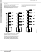
Unilift CC, KP, AP 4 Control panels 4. Control panels Model 112, simplex TM04 3408 4308 TM04 3395 4308 B Demand Dose C A Fig. 41 Model 112, simplex, control box Fig. 42 Dimensional drawings Technical data Model Full-load current [A] Number of phases Voltage [V] 96900631 112 7-15 1 120/208/240 A B C Shipping weight [lbs] 9.29 9.73 5.19 16 Shipping volume [cu ft] 1.06 Description Features Single-phase, simplex motor contactor and control panel.
Unilift CC, KP, AP 4 Control panels Model 122, duplex TM04 3402 4308 TM04 3396 4308 B Demand Dose C A Fig. 43 Model 122, duplex, control box Fig. 44 Dimensional drawings Technical data Dimensions [inches] Product number Model Full-load current [A] Number of phases Voltage [V] 96900632 122 7-15 1 120/208/240 A B C Shipping weight [lbs] 11.29 11.73 7.19 20 Shipping volume [cu ft] 2.16 Description Features Single-phase, duplex, alternating pump control panel with override.
Unilift CC, KP, AP 4 Control panels IFS 1, simplex TM04 3405 4308 TM04 3397 4308 B Timed dose C A Fig. 45 IFS 1, simplex, control box Fig. 46 Dimensional drawings Technical data Product number Model Full-load current [A] Number of phases Voltage [V] 96900636 IFS1 7-15 1 120/208/240 Description A B C Shipping weight [lbs] 9.29 11.73 5.19 20 Shipping volume [cu ft] 2.
Unilift CC, KP, AP 4 Control panels IFS 1, duplex TM04 3404 4308 TM04 3397 4308 B Timed dose C A Fig. 47 IFS 1, duplex, control box Fig. 48 Dimensional drawings Technical data Dimensions [inches] Product number Model Full-load current [A] Number of phases Voltage [V] 96900637 IFS1 7-15 1 120/208/240 Description A B C Shipping weight [lbs] 11.29 11.73 7.19 20 Shipping volume [cu ft] 2.
Unilift CC, KP, AP 5 Alarms 5. Alarms Tank Alert® I C TM04 3407 4308 TM04 3397 4308 B A Fig. 49 Tank Alert® I control box Fig. 50 Dimensional drawings Technical data Product number Model Full-load current [A] Number of phases Voltage [V] 96001042 TA1 5.0 1 120 Description Alert® Tank I is an asy-to-install, liquid level alarm system for indoor use.
Unilift CC, KP, AP 5 Alarms Tank Alert® 4X TM04 3408 4308 TM04 3400 4308 B A C Fig. 51 Tank Alert® 4X, control box Fig. 52 Dimensional drawings Technical data Product number Model Full-load current [A] Number of phases Voltage [V] 96001043 TA4X 5.0 1 120 Description Alert® Tank 4X is an asy-to-install liquid level alarm system which has a NEMA 4X enclosure for indoor or outdoor use.
Unilift CC, KP, AP 5 TM04 3406 4308 TM04 3398 4308 Alarms Tank Alert® AB Fig. 53 Tank Alert® AB, control box Fig. 54 Dimensional drawings Technical data Product number Model Full-load current [A] Number of phases Voltage [V] 96901182 TAAB 2.4 1 120 A B C Shipping weight [lbs] 4.05 6.86 2.37 4 Shipping volume [cu ft] 0.15 Description Features Tank Alert® AB is an asy-to-install liquid level alarm system with auto-reset and battery backup features for indoor use.
Unilift CC, KP, AP 6 Mechanical float switches Basins For Unilift Series Ejector basins Description Wide angle, piggyback connection Wide angle, piggyback connection Wide angle, without plug Wide angle, without plug Vertical, piggyback connection Vertical, piggyback connection Vertical, without plug Vertical, without plug Cable length [ft] Fits pump model 115 10 KP, AP and AP-B 96001059 115 25 KP, AP and AP-B 96901187 230 10 AP and AP-B 96001062 Voltage [V] Product number 230 25 AP
Unilift CC, KP, AP 6 Accessories Screw and gasket kits for basin covers Remarks Product number To be used with basin cover, product number • (8) 0.25" flat washers • (1) roll of gasket material • (1) 4" Adaptaflex/inlet New eight-screw design 96742102 96001008 • (8) 0.
Unilift CC, KP, AP 7 Pump and system sizing instructions Fixture unit values The information needed and steps required to properly size a wastewater pump and pumping system are listed below: 1. System capacity (GPM required) 2. Total dynamic head 3. Size of solids 4. Pump selection 5. Basin size 6. Simplex or duplex system The following pages explain how this information is obtained and used to properly size the pump and pumping system.
Unilift CC, KP, AP 7 Pump and system sizing instructions 2. Total dynamic head Tm 043425 4408 Dynamic head is expressed in feet of head (ft H2O). Total dynamic head is a combination of static head and friction loss: A. Static head The actual vertical distance of "lift" in feet from the minimum water level in the basin to the highest point in the discharge piping. Fig. 55 Illustration of static head for an ejector basin with pump and piping B.
Unilift CC, KP, AP 7 Pump and system sizing instructions Table B Friction losses for pipes (per 100 feet of piping): 1.25" diameter 1.5" diameter 2" diameter 2.5" diameter 3" diameter GPM 4 6 8 10 12 14 16 18 20 25 30 35 40 45 50 60 70 80 90 100 125 150 175 * Plastic Steel* 0.34 0.71 1.19 1.78 2.48 3.29 4.21 5.25 6.42 10.39 13.60 19.20 0.35 0.72 1.2 1.74 2.45 3.24 4.15 5.17 6.31 9.61 13.00 18.20 Plastic Steel* 0.33 .056 0.83 1.16 1.54 1.97 2.41 2.96 4.80 6.27 8.82 10.70 14.00 16.50 0.57 0.
Unilift CC, KP, AP 7 Pump and system sizing instructions 3. Size of solids If the building has a water closet of any kind, it will pass 2" solids and require a sewage pump. If it does not have a water closet, it will only need to pass at least 0.75" or smaller solids, and will require an effluent pump. 4. Pump selection Proceed as follows: 1. Go back to steps 1, 2 and 3 and find this information: • capacity (GPM) • total dynamic head required • solids handling requirements. 2.
Unilift CC, KP, AP 7 Pump and system sizing instructions 6. Simplex or duplex System Local plumbing codes will often determine whether a wastewater pumping system must be duplex (two pumps), or whether a simplex system (one pump) is sufficient. Most commercial applications are of the duplex type, however - not necessarily for the increased capacity offered by two pumps, but more for the standby safety factor that many municipalities require (public health concerns).
Unilift CC, KP, AP 8 Grundfos Product Center 8. Grundfos Product Center Online search and sizing tool to help you make the right choice. http://product-selection.grundfos.com SIZING enables you to size a pump based on entered data and selection choices. REPLACEMENT enables you to find a replacement product. Search results will include information on • the lowest purchase price • the lowest energy consumption • the lowest total life cycle cost. CATALOG gives you access to the Grundfos product catalog.
Unilift CC, KP, AP 8 Grundfos Product Center Grundfos GO Mobile solution for professionals on the GO! Grundfos GO is the mobile tool box for professional users on the go. It is the most comprehensive platform for mobile pump control and pump selection including sizing, replacement and documentation. It offers intuitive, handheld assistance and access to Grundfos online tools, and it saves valuable time for reporting and data collection.
© Copyright Grundfos Holding A/S 96900036 0315 ECM: 1155034 Grundfos Kansas City 17100 West 118th Terrace Olathe, Kansas 66061 Phone: 913-227-3400 Fax: 913-227-3500 www.grundfos.us Grundfos Canada 2941 Brighton Road Oakville, Ontario L6H 6C9 Canada Phone: +1-905-829-9533 Fax: +1-905-829-9512 www.grundfos.ca Grundfos México Boulevard TLC No. 15 Parque Industrial Stiva Aeropuerto C.P. 66600 Apodaca, N.L. Mexico Phone: 011-52-81-8144 4000 Fax: 011-52-81-8144 4010 www.grundfos.