
Install Instructions
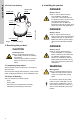
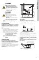
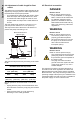
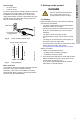
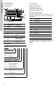
Table Of Contents

10
English (US)
6.2 Identification
6.2.1 Nameplate
Fig. 8 Nameplate
6.2.2 Type key
6.3 Functions
Pump with float switch
Automatic start and stop.
Pump without float switch
Manual external start and stop.
6.4 Pump construction
The main components of the pump appear from the
table below and figures A, B and C in the Appendix.
See page 15.
The position numbers are referred to in the cleaning
instructions in section 7.1 Cleaning the pump on
page 12.
TM06 9617 2517
Pos. Nameplate text Description
1 Prod. No. Product number
2 Imax Maximum current [A]
3 n Speed [min
-1
]
4 P1 Power input [Hp]
5Qmax
Maximum flow
[gal/min.]
6 Hmax Maximum head [ft]
7Tmax
Maximum liquid
temperature [°F]
8 P.c.:
Production code
(YYWW)
Example Unilift AP 35 B. 50. 08. A 1 V
Type range
Maximum
solids size [mm]
Pump type
Blank = AP Pump
B = AP Basic
Nominal diameter of outlet port
Power output P
2
/ 100 [W]
Level control
A=
Automatic operation
(with float switch)
Blank =
Manual operation
(without float switch)
Motor
1 = Single-phase
3 = Three-phase
Impeller
V = Vortex impeller
Type: UNILIFT AP XX.XX.XX.XX
Prod. No: XXXXXXXX
U: 1x115V~60Hz
Imax: 8,00 A n: XXXX min
-1
P1: X,XX hp XX,X lb
Qmax: XX gal/min Hmax: XX ft
P.c: XXXX
MADE IN HUNGARY
Pos. Description
6 Pump housing
37a O-ring
49 Impeller
55 Pump sleeve with motor
66 Washer
67 Lock nut
84 Inlet strainer
105 Shaft seal
182 Float switch
188a Screws
193 Screws