
User Guide

20
13. External forced-control signals
The pump has inputs for external signals for the forced-control
functions:
• Start/stop of pump.
• Digital function.
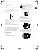
13.1 Start/stop input
Functional diagram: Start/stop input:
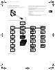
13.2 Digital input
By means of the R100, one of the following functions can be
selected for the digital input:
•Min. curve.
• Max. curve.
Functional diagram: Input for digital function:
14. External setpoint signal
By connecting an analog signal transmitter to the input for the
setpoint signal (terminal 4), it is possible to remote-set the head
(external setpoint).
The actual external signal (0-10 V, 0-20 mA, 4-20 mA) must be
selected via the R100, see section 12.3.2 Selection of external
setpoint signal.
If constant curve duty is selected by means of the R100, the
pump can be controlled by any controller.
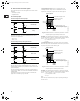
In proportional pressure mode, the setpoint can be set
externally within the range from ¼ of maximum head to the
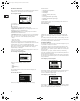
setpoint set on the pump or by means of the R100, fig. 29.
Fig. 29 Relation between the actual setpoint and the external
setpoint signal in proportional-pressure mode
Example: At a maximum head of 12 psi, a setpoint of 6 psi and
an external setpoint of 40%, the actual setpoint will be as follows:
H
actual
= (H
set
- 1/4 H
max.
) x %
external setpoint
+ 1/4 H
max.
= (6 - 12/4) x 40% + 12/4
= 4.2 psi
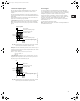
In constant pressure mode, the setpoint can be set externally
within the range from 1/8 of maximum head to the setpoint set on
the pump or by means of the R100, fig. 30.
Fig. 30 Relation between the actual setpoint and the external
setpoint signal in constant-pressure mode
Example: At a maximum head of 12 psi, a setpoint of 6 psi and
an external setpoint of 80%, the actual setpoint will be as follows:
H
actual
= (H
set
- 1/8 H
max.
) x %
external setpoint
+ 1/8 H
max.
= (6 - 12/8) x 80% + 12/8
= 5.1 psi
Max.:
When the input is activated, the pump is operating according to
the max. curve.
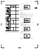
Start/stop (terminals 2 and 3)
Normal duty
Stop
Digital function (terminals 1 and 9)
Normal duty
Min. curve
Max. curve
Q
H
Q
H
Q
H
Q
H
Q
H
TM02 8988 1304TM02 8988 1304
0 10 V
0 20 mA
4 20 mA
Actual setpoint
¾ of maximum pump head
Setpoint set on pump
or with the R100
¼ of maximum pump head
External setpoint signal
Actual
setpoint
[H]
0 10 V
0 20 mA
4 20 mA
Actual setpoint
Maximum pump head
Setpoint set on pump
or with the R100
1/8 of maximum pump head
External setpoint signal
Actual
setpoint
[H]
Grundfos.bk Page 20 Thursday, November 11, 2010 11:21 PM