Grundfos.
Grundfos.bk Page 2 Thursday, November 11, 2010 11:21 PM LIMITED WARRANTY Products manufactured by GRUNDFOS PUMPS CORPORATION (Grundfos) are warranted to the original user only to be free of defects in material and workmanship for a period of 24 months from date of installation, but not more than 30 months from date of manufacture. Grundfos' liability under this warranty shall be limited to repairing or replacing at Grundfos' option, without charge, F.O.B.
Grundfos.bk Page 3 Thursday, November 11, 2010 11:21 PM CONTENTS Warning Page 1. General description 4 2. 2.1 2.2 2.3 2.4 2.5 2.6 Installation Motor cooling Outdoor installation Electrical connection Other connections Signal cables Bus connection cable 4 4 4 4 5 6 6 3. 3.1 3.2 3.3 E-circulator series 1000 Control modes Operating modes Factory setting 6 6 6 6 4. 4.1 4.2 4.3 4.4 Setting by means of control panel Setpoint setting Setting to max. curve duty Setting to min.
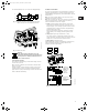
Grundfos.bk Page 4 Thursday, November 11, 2010 11:21 PM 1. General description 2.3 Electrical connection Grundfos E-Circulator pumps are pumps fitted with frequencycontrolled motors for single-phase mains connection. Note: The user or the installer is responsible for the installation of the correct earthing and protection according to valid national and local standards. All operations must be carried out by a qualified electrician.
Grundfos.bk Page 5 Thursday, November 11, 2010 11:21 PM 2.4 Other connections N N ELCB L PE L PE Fig. 2 TM02 0792 0101 For maximum backup fuse, see section 19.1 Supply voltage. Example of a mains-connected pump with mains switch, back-up fuses and additional protection The connection terminals of external potential-free contacts for start/stop and digital function, external setpoint signal, sensor signal, GENIbus, fault signal relay and communication cable are shown in fig. 4.
Grundfos.bk Page 6 Thursday, November 11, 2010 11:21 PM 2.5 Signal cables 3. E-circulator series 1000 • Use shielded cables having a cross-sectional area of min. 0.5 mm² and max. 1.5 mm² for external on/off switch, digital input, setpoint and sensor signals. • The shields of the cables must be connected to frame at both ends with good frame connection. They must be as close as possible to the terminals, fig. 5. 3.1 Control modes E-pumps can be set to two control modes, i.
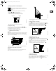
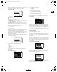
Grundfos.bk Page 7 Thursday, November 11, 2010 11:21 PM 4. Setting by means of control panel H At high system temperatures, the pump may be so hot that only the buttons should be touched to avoid burns. The pump control panel, fig. 10, incorporates the following: Buttons, • Light fields, yellow, for indication of setpoint. and , for setpoint setting. • Indicator lights, green (operation) and red (fault). Q Buttons TM00 7600 0304 Light fields Indicator lights Fig.
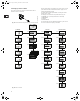
Grundfos.bk Page 8 Thursday, November 11, 2010 11:21 PM 5. Setting by means of R100 During communication, the R100 must be pointed at the control panel. When the R100 communicates with the pump, the red indicator light will flash rapidly. The pump is designed for wireless communication with the Grundfos remote control R100. The R100 offers additional possibilities of setting and status displays for the pump. TM02 0936 0501 The displays are divided into four parallel menus, fig. 16: Fig.
Grundfos.bk Page 9 Thursday, November 11, 2010 11:21 PM 5.1 Menu OPERATION Possible causes: When communication between the R100 and the pump has been established, the first display in this menu will appear. • • Undervoltage, 5.1.1 Setpoint setting • Overvoltage, • Too many restarts (after faults), • Overload, • Sensor signal outside signal range, Too high motor temperature, • Setpoint signal outside signal range, • Other fault.
Grundfos.bk Page 10 Thursday, November 11, 2010 11:21 PM 5.2.3 Display of actual value 5.3 Menu INSTALLATION 5.3.1 Selection of control mode The actually measured value of a connected sensor will appear in this display, e.g. 12 psi. 5.2.4 Display of actual speed Select one of the following control modes (see fig. 8): • Controlled, • Uncontrolled. The desired performance is set in section 5.1.1 Setpoint setting. Note: If the pump is connected to a bus (see section 8.
Grundfos.bk Page 11 Thursday, November 11, 2010 11:21 PM The table below shows the recommended controller settings: 5.3.3 Selection of external setpoint signal Kp System/ application Heating system 1) Cooling system2) 0.5 Ti 0.5 The input for external setpoint signal can be set to different signal types. Δp Select one of the following types: L [m] L < 5 m: 0.5 L > 5 m: 3 L > 10 m: 5 0.5 Δp • 0-10 V, • 0-20 mA, • 4-20 mA, • Not active.
Grundfos.bk Page 12 Thursday, November 11, 2010 11:21 PM 5.3.7 Selection of function for digital input Setting of the min. and max. curves in % of maximum performance. The digital input of the pump (terminal 1, fig. 4) can be set to different functions. • The max. curve can be adjusted within the range from maximum performance (100%) to min. curve. • The min. curve can be adjusted within the range from max. curve to 12% of maximum performance.
Grundfos.bk Page 13 Thursday, November 11, 2010 11:21 PM 7. External setpoint signal 8. Bus signal By connecting an analog signal transmitter to the input for the setpoint signal (terminal 4), it is possible to remote-set the setpoint. The pump enables serial communication via an RS-485 input. The communication is carried out according to the Grundfos bus protocol, GENIbus protocol, and enables connection to a building management system or another external control system.
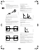
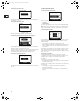
Grundfos.bk Page 14 Thursday, November 11, 2010 11:21 PM 9. E-circulator series 2000 Proportional-pressure control: 9.1 Functions The pump head is reduced at falling water demand and increased at rising water demand, see fig. 20. Most functions can be selected by means of the pump control panel. However, some functions can only be selected via the R100 or via bus. Constant-pressure control: The pump maintains a constant pressure, irrespective of water demand, see fig. 20. 9.1.
Grundfos.bk Page 15 Thursday, November 11, 2010 11:21 PM 9.2 Operating modes 11. Setting by means of control panel The following operating modes can be selected: At high system temperatures, the pump may be so hot that only the buttons should be touched to avoid burns. • Stop, • Min., • Normal (proportional pressure, constant pressure or constant curve), The pump control panel, fig. 22, incorporates the following: Max. • Buttons, • Light fields, yellow, for indication of setpoint.
Grundfos.bk Page 16 Thursday, November 11, 2010 11:21 PM 11.2 Changeover between proportional pressure and constant pressure When the buttons and are pressed simultaneously, the light fields will indicate the selected control mode, i.e. proportional pressure or constant pressure .
Grundfos.bk Page 17 Thursday, November 11, 2010 11:21 PM 12. Setting by means of R100 During communication, the R100 must be pointed at the control panel. When the R100 communicates with the pump, the red indicator light will flash rapidly. The pump is designed for wireless communication with the Grundfos remote control R100. The R100 offers additional possibilities of setting and status displays for the pump. The displays are divided into four parallel menus, fig. 28: 0.
Grundfos.bk Page 18 Thursday, November 11, 2010 11:21 PM 12.1 Menu OPERATION Possible causes: When communication between the R100 and the pump has been established, the first display in this menu will appear. • Too high motor temperature, • Undervoltage, 12.1.1 Setpoint setting • Overvoltage, • Too many restarts (after faults), • Overload, • Sensor signal outside signal range, • Setpoint signal outside signal range, • Other fault.
Grundfos.bk Page 19 Thursday, November 11, 2010 11:21 PM 12.2.3 Display of actual value 12.3.2 Selection of external setpoint signal The actually measured head will appear in this display. The input for external setpoint signal can be set to different signal types. Select one of the following types: 12.2.4 Display of actual speed • 0-10 V, • 0-20 mA, • 4-20 mA, • Not active. If Not active is selected, the setpoint set by means of the R100 or on the control panel will apply.
Grundfos.bk Page 20 Thursday, November 11, 2010 11:21 PM 13. External forced-control signals The pump has inputs for external signals for the forced-control functions: • Start/stop of pump. • Digital function. In proportional pressure mode, the setpoint can be set externally within the range from ¼ of maximum head to the setpoint set on the pump or by means of the R100, fig. 29. Actual setpoint [H] ¾ of maximum pump head 13.
Grundfos.bk Page 21 Thursday, November 11, 2010 11:21 PM In constant curve mode, the setpoint can be set externally within the range from the min. curve to the setpoint set on the pump or by means of the R100, fig. 31. 16. Priority of settings The start/stop and digital inputs will influence the number of possible settings. By means of the R100, the pump can always be set to max. curve duty or to stop.
Grundfos.bk Page 22 Thursday, November 11, 2010 11:21 PM 17. Indicator lights and fault signal relay Red Green The pump incorporates a fault signal relay with a potential-free changeover contact for external fault indication. The functions of the two indicator lights and the fault signal relay are as shown in the following table: TM00 7600 0304 The operating condition of the pump is indicated by the green and red indicator lights on the pump control panel, fig. 32. Fig.
Grundfos.bk Page 23 Thursday, November 11, 2010 11:21 PM 19. Technical data 19.1 Supply voltage 1 x 208-230V 60Hz PE. Cable: 0.5 - 1.5 mm² / 14-12 AWG. See nameplate. 19.4 Other technical data EMC (electromagnetic compatibility) EN 61 800-3. Residential areas - unlimited distribution, corresponding to CISPR 11, class B, group 1. Recommended fuse size Industrial areas - unlimited distribution, corresponding to CISPR 11, class A, group 1. Motor sizes from 0.33 to 1.5 hp: Max. 10 A.
Grundfos.bk Page 24 Thursday, November 11, 2010 11:21 PM 21. Installation in the USA and Canada In order to maintain the UL/cUL approval, these additional installation procedures must be followed. The UL approval is according to UL508C. 21.1 Electrical installation 21.1.1 Conductors Use 140/167°F (60/75°C) copper conductors only. 21.1.2 Torques Power terminal, M4: 2.35 Nm. Relay, M2.5: 0.5 Nm. Input control, M2: 0.2 Nm. 21.1.
Grundfos.
Grundfos.
Grundfos.bk Page 27 Thursday, November 11, 2010 11:21 PM U.S.A. Canada México GRUNDFOS Pumps Corporation 17100 West 118th Terrace Olathe, Kansas 66061 Phone: +1-913-227-3400 Telefax: +1-913-227-3500 GRUNDFOS Canada Inc. 2941 Brighton Road Oakville, Ontario L6H 6C9 Phone: +1-905 829 9533 Telefax: +1-905 829 9512 Bombas GRUNDFOS de México S.A. de C.V. Boulevard TLC No. 15 Parque Industrial Stiva Aeropuerto Apodaca, N.L.C.P. 66600 Phone: +52-81-8144 4000 Telefax: +52-81-8144 4010 Addresses revised 22.
Grundfos.bk Page 28 Thursday, November 11, 2010 11:21 PM Being responsible is our foundation Thinking ahead makes it possible Innovation is the essence L-EC-TL-001 11.10 Repl. L-EC-TL-001 07.10 US © 2005, 2010 Grundfos Pumps Corp. www.grundfos.com The name Grundfos, the Grundfos logo, and the payoff Be–Think–Innovate are registrated trademarks owned by Grundfos Management A/S or Grundfos A/S, Denmark. All rights reserved worldwide.