GRUNDFOS PRODUCT GUIDE TPE E-circulators In-line circulator pumps with integrated variable frequency drive 60 Hz
TPE E-circulators Table of contents 1. Pump data 3 Introduction 4 2. Performance range 6 3. Product range 7 4. Speed regulation 8 Operating conditions 9 Working pressure Fluid temperature Relative humidity Ambient temperature 9 9 9 9 5. 6. 7. 8. 9.
1 TPE E-circulators Pump data 1.
1 TPE E-circulators Pump data Introduction TP, TPE pumps are designed for applications such as • district heating systems • heating systems • air-conditioning systems • district cooling systems • water supply • industrial processes • industrial cooling. The pumps are available with either standard motors (TP) or electronically speed-controlled motors (TPE). The pumps are all single-stage, in-line centrifugal pumps with standard motor and mechanical shaft seal. The pumps are of the close-coupled type, i.
1 TPE E-circulators Example TP E 32 -160 /4 S -U -G -A Pump data Type key -BUBE Pump range Electronically speed-controlled pump series 1000/2000 Nominal diameter of suction and discharge flanges (mm) Maximum head [dm (decimeters)] Pole number S = TPE Series 2000 (with factory-fitted differential pressure sensor) U = NEMA motor dimensions G = ANSI or US flange Code for materials: A = Basic version Z = Bronze pump housing and motor stool Code for shaft seal (incl.
2 TPE E-circulators Performance range 2.
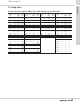
3 TPE E-circulators Product range 3. Product range TPE Series 2000 TPE SERIES 2000 with differential pressure sensor Cast iron product number Bronze product number Motor Hp TPE32-40/4 91136129 91136134 .33 TEFC 1 208-230 TPE32-80/2 91136104 91136109 .5 TEFC 1 208-230 Type Ph Volt GF 15/26 flange mount GF 40/43 flange mount TPE32-160/2 91136105 91136110 .75 TEFC 1 208-230 TPE40-40/4 91136130 91136135 .33 TEFC 1 208-230 TPE40-80/2 91136106 91136111 .
4 TPE E-circulators Speed regulation 4. Speed regulation Affinity equations WinCAPS and WebCAPS Normally, TPE pumps are used in applications characterized by a variable flow. Consequently, it is not possible to select a pump that is constantly operating at optimum efficiency. WinCAPS and WebCAPS are both selection programs offered by Grundfos. In order to achieve optimum operating economy, select the pump on the basis of the following criteria: • The max.
5 TPE E-circulators Operating conditions 5. Operating conditions Working pressure Maximum working pressure 145 psi (10 bar). Fluid temperature Maximum fluid temperature +284 °F (140 °C). Relative humidity Maximum 95%. Ambient temperature Maximum ambient temperature +104 °F (40 °C). Note: When motors installed more than 3000 ft (914 m) above sea level, the rated motor output will fall due to the low density and consequent low cooling effect of the air.
6 TPE E-circulators Pumped liquids 6. Pumped liquids List of pumped liquids Pumped liquids TP, TPE pumps are suitable for pumping thin, clean, non-aggressive and non-explosive liquids, not containing solid particles or fibers that may mechanically or chemically attack the pump; please see "List of pumped liquids" below. Examples of liquids: • Central heating system water (we recommend that the water meets the requirements of accepted standards on water quality in heating systems). • cooling liquids.
6 Pumped liquids Pumped liquids Notes Additional information Shaft seal TP <+194 °F (+90 °C) Groundwater AUUE >+194 °F (+90 °C) BUBE Boiler feed water <+248 °F (+120 °C) BUBE District heating water <+248 °F (+120 °C) BUBE <+194 °F (+90 °C) AUUE >+194 °F (+90 °C) BUBE <+194 °F (+90 °C) AUUE >+194 °F (+90 °C) BUBE pH>6.
7 TPE E-circulators TP, TPE pumps 7. TP, TPE pumps Materials Fig. 3 TM 00 9274 2002 TM03 4875 3206 TP, TPE TP Series pumps Fig. 4 Technical data Flow rate: up to 300 gpm (68 m3h) Head: up to 65 ft (20 m) Liquid temperature: –13 (–25 °C) to +284 °F (140 °C) Max. operating pressure: up to 145 psi (10 bar) Note: See Grundfos product guide L-TP-PG-001 for performance range.
7 Mechanical shaft seal Control Three types of unbalanced mechanical shaft seal are available as standard: Electronically controlled TPE pumps are suitable for demand-dependent performance control. • BUBE The BUBE shaft seal is a Grundfos rubber bellows seal with tungsten carbide/carbon seal faces and secondary seals of EPDM (standard seal).
8 TPE E-circulators TPE Series 2000 pumps 8. TPE Series 2000 pumps Applications TPE Series 2000 pumps have integrated speed control for automatic adaptation of performance to current conditions. TM03 0348 4904 This ensures that the energy consumption is kept at a minimum. H [ft] TPE 100% Technical data Flow rate: Head: Liquid temperature: Max. operating pressure: Motor sizes (single-phase): up to 200 gpm (45 m3h) up to 60 ft (18 m) –13 to +284 °F (–25 ° to 140 °C) 145 psi (10 bar) 0.33 to 1.
8 TPE E-circulators TPE Series 2000 pumps set to proportional pressure control continuously adjust the pump head to the system water requirement. The charts below show possible control modes of TPE Series 2000 pumps in different applications. Control mode Pump selection guidelines TPE Series 2000 pumps Differential proportional pressure TPE Series 2000 pumps are factory-set to proportional pressure.
8 TPE E-circulators TPE Series 2000 pumps Overview of functions E-pump functions TPE Series 2000 with single-phase MLE Setting via control panel: Setpoint Start/stop Max. curve Min. curve Alarm reset Constant/proportional pressure z z z z z z Reading via control panel: Setpoint Operating indication Fault indication z z z Setting via R100: Setpoint Start/stop Max. curve Min.
9 TPE E-circulators TPE Series 1000 pumps 9. TPE Series 1000 pumps H [ft] Fig. 6 Technical data Max. operating pressure: Motor sizes (single-phase): 0 0 Q [US GPM] In the QH-chart the 100 %-curve corresponds to the curve for a pump fitted with a standard fixed speed motor. TPE Series 1000 Flow rate: Head: Liquid temperature: 25% TM03 3609 0506 TM03 0347 4904 100% up to 200 gpm (45 m3h) up to 60 ft (18 m) –13 to +284 °F (–25 ° to 140 °C) 145 psi (10 bar) 0.33 to 1.
9 TPE E-circulators TPE Series 1000 pumps The charts below show possible control modes of TPE Series 1000 pumps in different applications. Control mode Application Constant curve Single-pipe heating systems. Systems with three-way valves. Heating and cooling surfaces. Chiller pumps. Constant differential pressure Systems with two-way valves. (Sensor is needed) Temperature control Single-pipe heating systems. Systems with three-way valves. Cooling towers. Chiller pumps.
9 TPE E-circulators E-pump functions TPE Series 1000 pumps Overview of functions TPE Series 1000, without sensor Setting via control panel: Setpoint Start/stop Max. curve Min. curve Alarm reset Constant/proportional pressure z z z z z Reading via control panel: Setpoint Operating indication Fault indication z z z Setting via R100: Setpoint Start/stop Max. curve Min.
10 TPE E-circulators Communication 10. Communication Communication with TPE pumps Remote control Communication with TPE pumps is possible via a central building management system, remote control (Grundfos R100) or a control panel. Central building management system The R100 remote control produced by Grundfos is available as an accessory. The operator communicates with the TPE pump by pointing the IR-signal transmitter at the control panel of the TPE pump terminal box.
11 TPE E-circulators Motors for TPE pumps 11. Motors for TPE pumps Motor The motor fitted on TPE pumps is a totally enclosed, fan-cooled standard motor with main dimensions and electrical tolerances to NEMA standards. Relative humidity: Enclosure class: Insulation class: Ambient temperature: Max. 95 % TEFC F, to IEC 85 Max. +104 °F Motor range Electronic speed controlled motors hp 2-pole/1 ph 4-pole/1 ph 0.34 0.50 MLE 0.75 MLE 1.0 1.5 MLE is Grundfos motor brands.
11 TPE E-circulators The variable frequency drive in the MLE motor of the TPE-pump is a highly integrated electronic unit. It is based on an integrated hybrid module developed by Grundfos. The functional blocks of the single-phase MLE motor variable frequency drive with PFC-circuit (Power Factor Correction) are shown in figure 10.
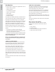
12 TPE E-circulators Curve charts 12. Curve charts How to read the curve charts H [m] H [ft] 14 45 TP 32 12 40 ISO 9906 Annex A 10 8 6 4 -160/2 60 Hz 35 30 -80/2 25 QH curve for the individual single-head pump. 20 15 The bold curve indicates the recommended performance range. 10 2 5 0 0 P2 [kW] P2 [hp] 0.5 0.7 0.4 0.4 0.3 50 Q [US GPM] -160/2 The power indicates pump input power (P2) -80/2 0 10 20 30 40 50 Q [US GPM] -160/2 35 30 25 20 0 40 0.1 8 2 30 0.
12 TPE E-circulators Curve charts TP, TPE 32-XX/2 H [m] H [ft] 14 45 TP 32 12 40 ISO 9906 Annex A 10 8 6 4 -160/2 60 Hz 35 30 -80/2 25 20 15 10 2 0 5 0 P2 [kW] P2 [hp] 0.5 0.7 0.4 0.2 0.3 NPSH [m] NPSH [ft] 50 Q [US GPM] -160/2 -80/2 0 10 20 30 40 50 Q [US GPM] -160/2 35 30 8 25 6 20 0 40 0.1 0.0 2 30 0.2 0.0 4 20 0.5 0.4 10 10 0.6 0.3 0.
12 Curve charts TPE E-circulators B5 M B2 B3 B1 H3 B4 H2 Z TM03 3669 0606 H1 D6 D7 D5 NPT 1/4 L3 D1 D2 D3 D4 L1 Technical data Pump type Motor type TPE TPE NEMA 56C P2 [HP] / Max speed [rpm] 0.50 Motor flange 56C NEMA 56C 3400 0.75 3400 56C Flange type US (1) D1 [Inch] / [mm] 1 7/16 35.
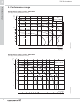
12 TPE E-circulators Curve charts TP, TPE 40-XX/2 H [m] 20 H [ft] TP 40 70 60 Hz -240/2 ISO 9906 Annex A 60 15 50 -160/2 40 10 5 -80/2 30 20 10 0 P2 [kW] 1.2 P2 [hp] 1.6 1.0 1.4 0.8 0.8 0.4 H [m] NPSH [ft] 40 6 4 2 0 -160/2 -80/2 0.2 0.0 8 -240/2 0.4 0.0 10 20 30 40 50 60 70 80 Q [US GPM] 1.2 0.6 12 10 1.0 0.6 0.
12 Curve charts TPE E-circulators B5 M B2 B3 B1 H3 B4 H2 TM03 3669 0606 Z H1 D6 D7 D5 NPT 1/4 L3 D1 D2 D3 D4 L1 Technical data Pump type Motor type TPE TPE NEMA 56C P2 [HP] / Max speed [rpm] 0.75 Motor flange 56C TPE NEMA 56C 3400 0.75 NEMA 56C 3400 56C 1.5 3400 56C Flange type US (1) D1 [Inch] / [mm] 1 11/16 41.8 1 11/16 US (1) 41.
12 TPE E-circulators Curve charts TP, TPE 50-XX/2 H [m] 20 H [ft] 18 60 16 14 12 10 8 6 4 2 0 50 20 10 0 1.6 0.4 0.2 20 40 60 80 100 Q [US GPM] -160/2 0.8 -80/2 0.4 0.0 NPSH [m] NPSH [ft] 4 0 1.2 0.0 5 -80/2 30 1.2 0.6 -160/2 40 P2 [hp] 0.8 60 Hz ISO 9906 Annex A P2 [kW] 1.
12 Curve charts TPE E-circulators B5 M B2 B3 B1 H3 B4 H2 TM03 3669 0606 Z H1 D6 D7 D5 NPT 1/4 L3 D1 D2 D3 D4 L1 Technical data Pump type TPE 50-80/2 Motor type NEMA 56C TPE 50-160/2 NEMA 56C P2 [HP] / Max speed [rpm] 0.75 3400 Motor flange 56C 1.5 3400 Flange type US (1) D1 [Inch] / [mm] 2 1/8 54 2 1/8 D2 [Inch] / [mm] 3 7/16 87 3 7/16 87 D3 [Inch] / [mm] 4 1/16 103 4 1/16 103 D4 [Inch] / [mm] 5 1/4 133 5 1/4 133 D5 [Inch] / [mm] 5/8 14.3 5/8 14.
12 TPE E-circulators Curve charts TP, TPE 32-XX/4 H [m] 3.5 3.0 H [ft] 12 -40/4 TP 32 60 Hz 11 ISO 9906 Annex A 10 9 2.5 2.0 1.5 1.0 0.5 0.0 P2 [kW] 0.08 0.06 0.04 8 7 6 5 4 3 2 1 0 P2 [hp] 0 5 10 15 20 25 30 35 40 Q [US GPM] -40/4 0.12 0.10 0.08 0.06 0.04 0.02 0.02 0.00 0.00 NPSH [m] NPSH [ft] 3.0 10 2.5 8 2.0 1.5 1.0 0 5 10 15 20 25 30 35 40 Q [US GPM] -40/4 6 4 0.5 2 0.
12 Curve charts TPE E-circulators B5 M B2 B3 B1 H3 B4 H2 Z TM03 3669 0606 H1 D6 D7 D5 NPT 1/4 L3 D1 D2 D3 D4 L1 Technical data TPE 32-40/4 Pump type Motor type NEMA 56C P2 [HP] / Max speed [rpm] 0.33 Motor flange 56C 1690 Flange type US (1) US D1 [Inch] / [mm] 1 7/16 35.
12 TPE E-circulators Curve charts TP, TPE 40-XX/4 H [m] 4.0 3.5 H [ft] 60 Hz ISO 9906 Annex A 3.0 10 2.5 8 2.0 TP 40 -40/4 12 6 1.5 1.0 0.5 0.0 P2 [kW] 0.16 0.14 0.12 0.10 0.08 0.06 0.04 0.02 4 2 0 P2 [hp] 0 30 40 50 60Q [US GPM] -40/4 0.16 0.12 0.08 0.04 0.00 NPSH [m] NPSH [ft] 0 2.0 20 0.20 0.00 2.5 10 10 20 30 40 50 60Q [US GPM] 8 -40/4 6 1.5 1.0 0.5 0.
12 Curve charts TPE E-circulators B5 M B2 B3 B1 H3 B4 H2 Z TM03 3669 0606 H1 D6 D7 D5 NPT 1/4 L3 D1 D2 D3 D4 L1 Technical data TPE 40-40/4 Pump type Motor type NEMA 56C P2 [HP] / Max speed [RPM] 0.33 Motor flange 56C 1690 Flange type US (1) D1 [Inch] / [mm] 1 11/16 D2 [Inch] / [mm] 2 7/8 73 D3 [Inch] / [mm] 3 15/16 99 5 127 D4 [Inch] / [mm] 41.8 D5 [Inch] / [mm] 11/16 16 D6 [Inch] / [mm] 2 1/16 52 D7 [Inch] / [mm] 2 9/16 64.
12 TPE E-circulators Curve charts TP, TPE 50-XX/4 H [m] 4.5 4.0 3.5 H [ft] 2.5 8 1.0 6 4 0.5 2 0.0 0 P2 [kW] P2 [hp] 0.20 0.18 0.16 0.14 0.12 0.10 0.08 0.06 0.04 0.02 0.00 0.28 0.00 NPSH [m] NPSH [ft] 20 30 40 50 60 70 80 Q [US GPM] -40/4 0.16 0.12 0.08 0.04 1.25 4 0.50 10 0.24 5 0.75 0 0.20 1.50 1.00 ISO 9906 Annex A 12 10 1.5 60 Hz -40/4 3.0 2.0 TP 50 14 0 10 20 30 40 50 60 70 80 Q [US GPM] 110 -40/4 3 2 0.25 1 0.
12 Curve charts TPE E-circulators B5 M B2 B3 B1 H3 B4 H2 Z TM03 3669 0606 H1 D6 D7 D5 NPT 1/4 L3 D1 D2 D3 D4 L1 Technical data TPE 50-40/4 Pump type Motor type NEMA 56C P2 [HP] / Max speed [rpm] 0.33 Motor flange 56C Flange type US (1) D1 [Inch] / [mm] 2 1/8 53 D2 [Inch] / [mm] 3 1/2 87.5 D3 [Inch] / [mm] 4 1/8 103.2 D4 [Inch] / [mm] 5 1/4 133 D5 [Inch] / [mm] 5/8 14.3 D6 [Inch] / [mm] 2 1/2 63 D7 [Inch] / [mm] 3 1/8 77.
12 TPE E-circulators Curve charts TP, TPE 80-XX/4 H [m] 4.0 3.5 H [ft] 10 2.5 8 1.5 1.0 6 4 0.5 2 0.0 0 P2 [kW] 0.4 P2 [hp] 0.3 0.4 0.2 60 Hz ISO 9906 Annex A 12 3.0 2.0 TP 80 -40/4 14 0 20 40 60 80 100 120 140 Q [US GPM] 0.5 -40/4 0.3 0.2 0.1 0.1 0.0 0.
12 Curve charts TPE E-circulators B5 M B2 B3 B1 H3 B4 H2 Z TM03 3669 0606 H1 D6 D7 D5 NPT 1/4 L3 D1 D2 D3 D4 L1 Technical data TPE 80-40/4 Pump type Motor type NEMA 56C P2 [HP] / Max speed [rpm] 0.50 Motor flange 56C Flange type 3” ANSI 125lb..RF. 1690 D1 [Inch] / [mm] 3 3/16 80.
12 TPE E-circulators Curve charts TP, TPE 100-XX/4 H [m] 5.0 4.5 4.0 3.5 H [ft] 2.5 8 1.0 6 4 0.5 2 0.0 0 P2 [kW] P2 [hp] 0.48 0.65 0.44 0.60 0.40 0.55 0.36 0.32 ISO 9906 Annex A -40/4 12 10 1.5 60 Hz 14 3.0 2.0 TP 100 16 0 20 40 60 80 100 120 140 160 Q [US GPM] -40/4 0.50 0.45 0.40 3.5 NPSH [ft] 10 2.5 8 1.5 1.0 20 40 60 80 100 120 140 160 Q [US GPM] -40/4 12 3.0 2.0 0 6 4 0.5 2 0.
12 Curve charts TPE E-circulators B5 M B2 B3 B1 H3 B4 H2 TM03 3669 0606 Z H1 D6 D7 D5 NPT 1/4 L3 D1 D2 D3 D4 L1 Technical data TPE 100-40/4 Pump type Motor type NEMA 56C P2 [HP] / Max speed [rpm] 1.0 Motor flange 56C Flange type 3” ANSI 125lb..RF.
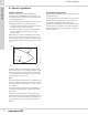
13 TPE E-circulators Installation 13. Installation Mechanical installation Elimination of noise and vibrations TP, TPE pumps can be installed in horizontal and vertical pipes. In order to achieve optimum operation and minimum noise and vibration, consider vibration dampening of the pump. TM03 3064 0206 Noise and vibration are generated by the revolutions of the motor and pump and by the flow in pipes and fittings.
13 TPE E-circulators The selection of the right vibration damper requires the following data: • forces transmitted through the damper • motor speed considering speed control, if any • required dampening in % (suggested value is 70 %). Expansion joints with limit rods can be used to reduce the effects of the expansion/contraction forces on the pipework. Anchor the pipes in such a way that they do not stress the expansion joints and the pump.
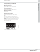
13 TPE E-circulators Carry out electrical connection and protection in accordance with local regulations. • Electronically speed-controlled pumps must always be correctly grounded. • Single-phase standard motors incorporate a thermal switch and require no additional thermal motor protection. Note: Carry out the mains connection of the pump as shown in the diagram inside the terminal box cover. Use screened cables (min. 0.5 mm2) for external on/off switch, digital input, sensor and and setpoint signals.
13 TPE E-circulators Other connections TPE See the wiring diagrams for instructions how to connect external potential-free contacts for start/stop and digital function, external setpoint signal and fault signal. Installation Note: • As a precaution, separate the wires from each other by reinforced insulation in their entire lengths. • If no external on/off switch is connected, maintain the connection across terminals 2 and 3.
14 TPE E-circulators Accessories 14. Accessories Sensors for circulation applications Differential pressure sensor kit • • • • • • • • • 1 1 1 2 1 1 2 2 5 sensor incl. 4.
15 TPE E-circulators Further product documentation 15. Further product documentation WebCAPS WebCAPS is a Web-based Computer Aided Product Selection program available on www.grundfos.com. WebCAPS contains detailed information on more than 185,000 Grundfos products in more than 20 languages. In WebCAPS, all information is divided into 6 sections: • Catalog • Literature • Service • Sizing • Replacement • CAD drawings.
15 TPE E-circulators Further product documentation Sizing 0 1 This section is based on different fields of application and installation examples, and gives easy step-by-step instructions in how to • select the most suitable and efficient pump for your installation • carry out advanced calculations based on energy consumption, payback periods, load profiles, life cycle costs, etc.
16 TPE E-circulators Submittal data sheet 16.
Being responsible is our foundation Thinking ahead makes it possible Innovation is the essence L-TPE-PG-01 10/11 US Repl. 07/10 The name Grundfos, the Grundfos logo, and the payoff Be–Think–Innovate are registrated trademarks owned by Grundfos Management A/S or Grundfos A/S, Denmark. All rights reserved worldwide. © 2006, 2010 Grundfos Pumps Corp. GRUNDFOS Pumps Corporation 17100 West 118th Terrace Olathe, Kansas 66061 Phone: +1-913-227-3400 Telefax: +1-913-227-3500 GRUNDFOS Canada Inc.