
User Guide

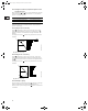

15
9.2 Operating modes
The following operating modes can be selected:
•Stop,
•Min.,
• Normal (proportional pressure, constant pressure or constant
curve),
•Max.
The operating modes can all be set on the pump control panel.
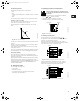
9.2.1 Max. or min. curve duty
The pump can be set to operate according to the max. or min.
curve, like an uncontrolled pump, see fig. 21.
This operating mode is available, irrespective of the control
mode.
Fig. 21 Max. and min. curves
The min. curve can be used in periods in which a minimum flow is
required.
The max. curve can for instance be used in connection with the
venting procedure during installation.
If the electricity supply to the pump is disconnected, the pump
setting will be stored.
The remote control R100 offers additional possibilities of setting
and status displays, see section 5. Setting by means of R100.
9.3 Factory setting
The pumps have been factory-set to proportional pressure.
The head corresponds to 50% of the maximum pump head (see
data sheet for the pump).
Many systems will operate satisfactorily with the factory setting,
but most systems can be optimized by changing this setting.
Other pump settings are marked with bold-faced type under each
individual display in sections 12.1 Menu OPERATION and
5.3 Menu INSTALLATION.
10. Setting the pump
For the setting of the pump, use:
• control panel.
• R100 remote control.
• bus communication (not described in detail in these
instructions. Contact Grundfos).
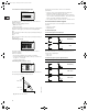
11. Setting by means of control panel
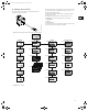
The pump control panel, fig. 22, incorporates the following:
• Buttons, and , for setpoint setting.
• Light fields, yellow, for indication of setpoint.
• Indicator lights, green (operation) and red (fault).
Fig. 22 Control panel
11.1 Setting of pump head
The pump head is set by pressing the button or .
The light fields on the control panel will indicate the head set
(setpoint). See the following examples.
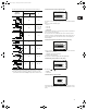
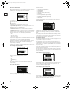
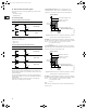
Figure 23 shows that the light fields 5 and 6 are activated,
indicating a desired head of 3 psi at maximum flow. The setting
range lies between ¼ and ¾ of maximum head.
Fig. 23 Pump in proportional-pressure control mode
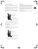
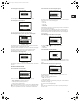
Figure 24 shows that the light fields 5 and 6 are activated,
indicating a desired head of 3.1 psi. The setting range lies
between 1/8 of maximum head and maximum head.
Fig. 24 Pump in constant-pressure control mode
TM02 5547 4596
Q
H
Max.
Min.
At high system temperatures, the pump may be
so hot that only the buttons should be touched to
avoid burns.
TM00 7600 0304TM02 8986 1304TM02 8987 1304
Indicator lights
Light fields
Buttons
H m
QQ
0
1
2
3
4
5
[psi]
5
4
3
2
1
0
Q
Q
H m
[psi]
Grundfos.bk Page 15 Thursday, November 11, 2010 11:21 PM