
User Guide

12
5.3.7 Selection of function for digital input
The digital input of the pump (terminal 1, fig. 4) can be set to
different functions.
Select one of the following functions:
• Min. (min. curve),
• Max. (max. curve).
The selected function is activated by closing the contact between
terminals 1 and 9 (fig. 4). See also section 6.2 Digital input.
Min.:
When the input is activated, the pump is operating according to
the min. curve.
Max.:
When the input is activated, the pump is operating according to
the max. curve.
5.3.8 Setting of sensor
The setting of the sensor is only carried out in the case of
controlled operation.
Select the following:
• Sensor output signal (0-10 V, 0-20 mA or 4-20 mA),
• sensor measuring unit (bar, mbar, m, kPa, psi, ft, m³/h, m³/s,
l/s, gpm, °C, °F or %) and
• sensor measuring range.
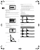
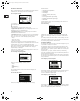
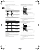
5.3.9 Setting of min. and max. curves
Set the min. and max. curves in % of maximum performance if
the operating range must be reduced, fig. 17.
Fig. 17 Min. and max. curves.
Setting of the min. and max. curves in % of maximum
performance.
• The max. curve can be adjusted within the range from
maximum performance (100%) to min. curve.
• The min. curve can be adjusted within the range from max.
curve to 12% of maximum performance. The pump has been
factory-set to 24% of maximum performance.
• The operating range lies between the min. and max. curves.
6. External forced-control signals
The pump has inputs for external signals for the forced-control
functions:
• Start/stop of pump.
• Digital function.
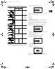
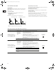
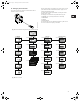
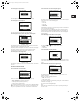
6.1 Start/stop input
Functional diagram: Start/stop input:
6.2 Digital input
By means of the R100, one of the following functions can be
selected for the digital input:
•Min. curve.
• Max. curve.
Functional diagram: Input for digital function:
TM00 7747 1896
Q
H
Operating ra
n
ge
100%
Max. curve
Min. curve
12%
Start/stop (terminals 2 and 3)
Normal duty
Stop
Digital function (terminals 1 and 9)
Normal duty
Min. curve
Max. curve
Q
H
Q
H
Q
H
Q
H
Q
H
Grundfos.bk Page 12 Thursday, November 11, 2010 11:21 PM