
User Guide

11
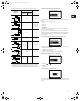
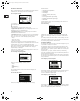
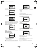
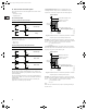
The table below shows the recommended controller settings:
1) Heating systems are systems in which an increase in pump
performance will result in a rise in temperature at the sensor.
2) Cooling systems are systems in which an increase in pump
performance will result in a drop in temperature at the sensor.
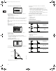
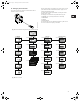
5.3.3 Selection of external setpoint signal
The input for external setpoint signal can be set to different signal
types.
Select one of the following types:
• 0-10 V,
• 0-20 mA,
• 4-20 mA,
• Not active.
If Not active is selected, the setpoint set by means of the R100 or
on the control panel will apply.
The setpoint set is the maximum value of the external setpoint
signal, see section 7. External setpoint signal. The actual value of
the external setpoint can be read from section 5.2.1 Display of
actual setpoint.
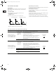
5.3.4 Selection of fault, operating or ready signal relay
It can be selected in which situation the relay should be activated:
• Fault (fault indication),
• Operation (operating indication),
• Ready (ready indication).
See section 17. Indicator lights and fault signal relay.
5.3.5 Blocking of the buttons on the pump
The buttons and on the pump can be set to:
• Active,
• Not active.
5.3.6 Allocation of pump number
A number between 1 and 64 can be allocated to the pump. In the
case of bus communication, a number must be allocated to each
pump.
System/
application
K
p
T
i
Heating
system
1)
Cooling
system
2)
0.5 0.5
0.5
L < 5 m: 0.5
L > 5 m: 3
L > 10 m: 5
0.5 0.5
0.5 0.5
0.5 -0.5 10 + 5L
0.5 10 + 5L
0.5 -0.5 30 + 5L
Δp
L [m]
Δp
p
Q
L [m]
t
L [m]
Δt
L [m]
t
Grundfos.bk Page 11 Thursday, November 11, 2010 11:21 PM