
User Guide

10
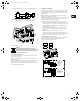
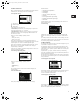
5.2.3 Display of actual value
The actually measured value of a connected sensor will appear in
this display, e.g. 12 psi.
5.2.4 Display of actual speed
Tolerance: ±5%
The actual pump speed will appear in this display.
5.2.5 Display of input power and power consumption
Tolerance: ±10%
This display shows the actual pump input power from the mains
supply. The power is displayed in W or kW.
The pump power consumption can also be read from this display.
The value of power consumption is an accumulated value
calculated from the pump’s birth and it cannot be reset.
5.2.6 Display of operating hours
Tolerance: ±2%
The value of operating hours is an accumulated value and cannot
be reset.
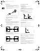
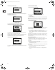
5.3 Menu INSTALLATION
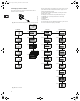
5.3.1 Selection of control mode
Select one of the following control modes (see fig. 8):
• Controlled,
• Uncontrolled.
The desired performance is set in section 5.1.1 Setpoint setting.
Note: If the pump is connected to a bus (see section 8. Bus sig-
nal), it is not possible to select the control mode via the R100.
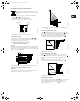
5.3.2 Setting of controller
In this display, the gain (K
p
) and the integral-action time (T
i
) of the
built-in PI controller can be set if the factory setting is not the
optimum setting:
•The gain (K
p
) is set within the range from 0.1 to 20.
• The integral-action time (T
i
) is set within the range from 0.1 to
3600 s. If 3600 s is selected, the controller will function as a
P controller.
Furthermore, it is possible to set the controller to inverse control
(if the setpoint is increased, the speed will be reduced). In the
case of inverse control, the gain (K
p
) must be set within the range
from –0.1 to –20.
Setting the PI controller:
For most applications, the factory setting of the controller
constants K
p
and T
i
will ensure optimum pump operation. In the
following cases, a change of the setting can be useful or
necessary.
A change of the T
i
setting can be useful:
• in a differential-pressure control system if the sensor is placed
far away from the pump.
A change of the T
i
setting, and in some cases the K
p
setting, may
be necessary:
• if the pump is controlled on the basis of temperature or
differential temperature.
• If no sensor is connected to the pump, “–” will appear in the
display.
Grundfos.bk Page 10 Thursday, November 11, 2010 11:21 PM