
Install Instructions

INSTALLATION PROCEDURE
The timer control accessory is electrically connected and
mounted to the circulator terminal box.
Install as follows:
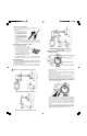
1. Remove the retaining screw in
the existing terminal box cover
and remove the cover. The timer
control unit replaces this cover.
2. See “5. Electrical Hookup”,
for specific wiring instructions
for hookup as an individual
component or in series with the
thermostatic control.
3. After wiring is completed and checked, install the timer control
unit onto the terminal box bracket and reinsert the terminal box
screw. Be careful not to bind or leave exposed any terminal box
wires.
4. Installing the Thermostatic Control
INSTALLATION PROCEDURE
1. The thermostatic control is a surface
temperature sensing device that must
be in contact with the system piping to
operate properly. Separate models in
clude clip-on mounts for 3/4” (7/8”
O.D.) and 1/2” (5/8” O.D.) copper
tubing. These models are also suitable
for use with 12” and 3/8” schedule 40
steel pipe, respectively.
2. See “5 Electrical Hook-up”, for specific wiring instructions for
hook-up as an individual component or in series with the timer
control.
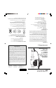
5. Electrical Hook-up
All electrical work should be performed by a qualified electrician in
accordance with the latest edition of the National Electric Code and
local codes and regulations.
Verify the electrical supply to be certain the voltage, phase and fre-
quency match that of the circulator and accessory components.
6. Setting and Operating the Timer Control and
Starting the Pump
NOTE: Before the circulator is started, the system must be filled
with liquid and vented.
1. Set the timer switch to the actual time by turning the program-
ming ring in the direction of the arrow until the timing arrow points
to the actual time on the ring.
2. Switch on the power supply to the circulator and set the manual
switch to the “ON” position. The circulator will now start.
3. Set the required “ON”/”OFF” times on the programming ring by
pushing the programming tabs either away from or toward the
center of the ring. Tabs pushed away from the center indicate
circulator switched ”ON” while tabs pushed toward the center in
dicate circulator switched “OFF”.
4. Set the manual switch to the “TIMER” position. The circulator will
now start/stop according to the settings of the programming tabs.
5. For continuous operation, set the manual switch to the “ON” po-
sition. To switch the circulator off, set the manual switch to the
“OFF” position. The “ON”/”OFF” modes may be used without af-
fecting the function of either the programming ring or the timer
switch.
6. In case of power outage the timer will not keep time. After power
has been restored, the correct time of day must be reset by rotat-
ing the programming ring in the direction of the arrow until the
timing arrow points to the actual time on the ring.
CAUTION: Do not energize pump until properly installed