
Install Instructions

Page 12
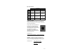
wiring may be shorted, there may be moisture in the
070 or the 070 may be defective. To test for a
defective 070 sensor, measure the resistance directly at
the 070 sensor location.
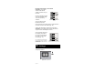
Replace the front cover of the 070 sensor enclosure.
Test the Power Supply or Heat Demand.
Make sure exposed wires and bare terminals are not in
contact with other wires or grounded surfaces. Turn on
the power or provide a heat demand and measure the
voltage across the leads. The voltmeter should read
between plus and minus 4 volts of the supplied voltage.
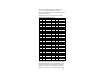
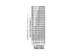
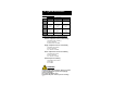
Temperature Resistance Temperature Resistance
o
F
o
C
ΩΩ
ΩΩ
Ω
o
F
o
C
ΩΩ
ΩΩ
Ω
-50 -46 490,813 90 32 46,218
-45 -43 405,710 95 35 7,334
-40 -40 336,606 100 38 5,828
-35 -37 280,279 105 41 5,210
-30 -34 234,196 110 43 4,665
-25 -32 196,358 115 46 4,184
-20 -29 165,180 120 49 3,760
-15 -26 139,402 125 52 3,383
-10 -23 118,018 130 54 3,050
-5 -21 100,221 135 57 2,754
0 -18 85,362 140 60 2,490
5 -15 72,918 145 63 2,255
10 -12 62,465 150 66 2,045
15 -9 53,658 155 68 1,857
20 -7 46,218 160 71 1,689
25 -4 39,913 165 74 1,538
30 -1 34,558 170 77 1,403
35 2 29,996 175 79 1,281
40 4 26,099 180 82 1,172
45 7 22,763 185 85 1,073
50 10 19,900 190 88 983
55 13 17,436 195 91 903
60 16 15,311 200 93 829
65 18 13,474 205 96 763
70 21 11,883 210 99 703
75 24 10,501 215 102 648
80 27 9,299 220 104 598
85 29 8,250 225 107 553
Temperature/Resistance Chart