Grundfos MixiMizer ™ Installation & Operating Instructions Pumps Incorporating the (MR) Mixing Reset Control 1. 2. 3. 4. 5. Shipment Inspection Page 3 General Page 3 Operational Limits Page 4 Pump Installation Page 6 Installation Requirements Page 7 6. 7. 8. 9. 10.
CONGRATULATIONS! You are now the fortunate owner of a MixiMizer TM PUMP. It has been carefully inspected and tested before shipment. It should give you long, efficient, trouble-free service. For maximum performance and reliability, please follow the simple instructions in this manual. Since mixing by a variable speed injection pump is a relatively new concept, there are a few simple piping details that should be considered.
When installing and using this electrical equipment, basic safety precautions should always be followed, including the following: The installer must ensure that this control and its wiring are isolated and/or shielded from strong sources of electromagnetic noise. Conversely, this Class B digital apparatus complies with Part 15 of the FCC Rules and meets all requirements of the Canadian InterferenceCausing Equipment Regulations.
1. Shipment Inspection Check the contents of this package. Care should be taken to ensure the pump is NOT dropped or mishandled; dropping will damage the pump. Grundfos MixiMizer Injection Pump Package Includes: • One Grundfos UP15-42 MixiMizer pump with integral control or one Grundfos UP43-64 MixiMizer pump with integral control. Two Water Temperature Sensors 071 – Pre-wired into control unit with 6’ of wire. One 6’ line cord with 115 V plug, pre-wired into control unit.
• • • • Pump Exercising: After every three days of no operation, the control will exercise the pump for 10 seconds. The % of Pump Performance LED will be on during exercising. Post Purge: A 20 second post purge is available once the heat demand is removed or control enters WWSD. The purging holds the last speed used. As variable speed output modulates, the control flashes the % of Pump Performance LED on for ¼ second and off for ¼ to 2 1/2 seconds.
UP15-42FC/MR 115V 60 Hz MixiMizer Pump UP15-42BUC5/MR 115V 60 Hz MixiMizer Pump UP15-42BUC7/MR 115V 60 Hz MixiMizer Pump Maximum fluid temperature: 200°F (95°C) Maximum ambient: • 115°F (46°C) with control module vertical (Fig. 4a). • 115°F (46°C) with control module under pump and horizontal (Fig. 4B). • 105°F (40°C) with control module on top of pump and horizontal (Fig 4B).
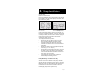
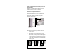
4. Pump Installation Remove the control from the pump and install pump in injection loop Position of terminal box: Prefered installation of the pump will have the terminal box located to one side of the pump or the other, with the conduit entry down. Figure 4A - Prefered Terminal Box Orientation Figure 4B - Optional Terminal Box Orientation (see Operational Limits) If the terminal box position needs to be changed, it is best to do so before installation.
Figure 4C The pump must be installed with the motor shaft positioned horizontally. Under no circumstances should the pump be installed with the shaft vertical or where the shaft falls below the horizontal plane (Fig.4C). Recommended DO NOT Optional Mount Motor Shaft in Vertical Position 5. Installation Requirements • • • • • • • Thoroughly clean and flush the system prior to pump installation Ensure that water does not enter the terminal box during the installation process.
edition of the National Electrical Code, local codes and regulations. Install a 2” x 4” duplex electrical box to house low voltage wiring for connection to the control. Outdoor Air Temperature Sensor 070 The Outdoor Air Temperature Sensor 070 includes a 10 kW thermistor which provides an accurate measurement of the outdoor temperature. The 070 sensor is protected by a white U.V. resistant PVC plastic enclosure (Fig. 6A & 6B).
• • • In order to prevent heat transmitted through the wall from affecting the sensor reading, it may be necessary to install an insulating barrier behind the enclosure. The 070 should be mounted on a wall which best represents the heat load on the building (a northern wall for most buildings or a southern facing wall for buildings with large south facing glass areas). The 070 should not be exposed to heat sources such as ventilation or window openings.
• sensor location requires that the fluid is thoroughly mixed within the pipe before it reaches the sensor. Locate the labels attached to each sensor. One sensor will be identified as the return sensor and one will be identified as the supply sensor. (Fig 6F & 6G) Mount the return sensor to the return piping of the boiler loop. Mount the supply sensor to supply piping of the system loop.
• Com (–) terminal on the control and not to earth ground. Run wires from the 24-30 V (ac) power source or heat demand to the electrical box for the wiring. Use a clean power source to ensure proper operation. Wiring and Testing the Outdoor Air Temperature Sensor 070 CAUTION: No wires should be connected to the control during testing. CAUTION: Do not apply voltage to the 070 at any time as damage to the 070 may result.
wiring may be shorted, there may be moisture in the 070 or the 070 may be defective. To test for a defective 070 sensor, measure the resistance directly at the 070 sensor location. Replace the front cover of the 070 sensor enclosure.
Electrical Connections To The Control CAUTION: The installer should confirm that no voltage is present at any of Demand the wires. Dem / I Pull wires through the wiring cover and install the wiring cover over the wiring chamber. Com (-) Out / V Figure 7B - Electrical (demand) connections to the control 24 V (ac) Power or Heat Demand Connections: Connect the 24 V (ac) power supply or heat demand to terminals “Demand” and “DEM/I” (Fig. 7B).
Dip switch settings POSITION SWITCH ON OFF DEFAULT A Permanent Demand External Demand ON position Permanent Demand B Max system supply set at 140oF Max system supply feature is off ON position supply set at 140oF C Boiler return minimum set at 135oF Boiler return minimum feature is off ON position minimum set at 135oF Heating curve No shift Heating Curve 5oF Parallel shift On position No shift D Heating Curve Dial Before adjusting the dial settings, read through the sequence of operation
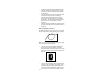
Heating Curve 3.6 3.0 2.6 2.2 2.0 1.8 230 220 1.6 210 System Design Temperature, °F 200 1.4 190 180 1.2 170 1.0 160 150 0.8 140 130 0.6 120 110 0.4 100 90 0.
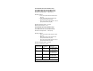
Page 16 Heating Curve Table (Warm Weather Shut Down = 70°F)
If the design supply water temperature is unknown, the Heating Curve dial can be set to a trial value using the typical design supply temperatures given below. Typical design supply temperatures: • Hydronic radiant floors: 100 to 130°F (38 to 54°C) • Baseboard convectors: 160 to 190°F (71 to 88°C) • Fan coils: 180 to 210°F (82 to 99°C) Factory default setting is 1.0. Install control onto the pump. Insert the 115 V plug on the line cord from the pump into a properly grounded 115 V outlet.
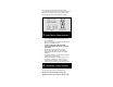
9. Error Messages and Control Response Whenever a fault is detected in any of the sensors, the control LEDs will flash in a specific way, to indicate the location of the problem, and the control will assume a specific operating condition. • Call For Heat LED is flashing (Fig 9A): – Then the outdoor sensor is short or open circuit – And the control assumes an outdoor temperature of 30°F Figure 9A - Control Lights (Call For heat) • Pump Performance Reduced LED is flashing (Fig.
10.
+ - ON Made in Canada 100µ OFF AB C D MOV 1 0.35 or 0.5 VA Triac 0.1µF wire clamp Sup Demand Com Dem / I conductors only 106-1 crystal Com (-) 106-0 0.1µF ® Ret Use copper R 0.1µF Out / V Meets Class B: Canadian ICES FCC Part 15 Power: 120 V ±10% 50/60 Hz 240 VA Var. Speed: 120 V (ac) 1.8 A, 1/12 hp 10µF Demand: 20 - 30 V (ac) 0.
Limited Warranty Products manufactured by GRUNDFOS PUMPS CORPORATION (GRUNDFOS) are warranted to the original user only to be free of defects in material and workmanship for a period of 18 months from date of installation, but not more than 24 months from date of manufacture. GRUNDFOS' liability under this warranty shall be limited to repairing or replacing at GRUNDFOS' option, without charge, F.O.B. GRUNDFOS' factory or authorized service station, any product of GRUNDFOS manufacture.