
Instructions / Assembly
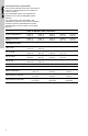
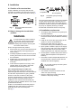
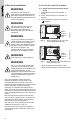


Table Of Contents

6
English (US)
5. Electrical installation
The proper operating voltage and other
electrical information can be found on the
nameplate attached to the top of the motor.
Depending on pump model, the motor has either
built-in, automatic, resetting of thermal
protection or is impedance protected and in
either case does not require additional external
protection. The temperature of the windings will
never exceed allowable limits, even if the rotor is
locked.
Wire sizes should be based on the ampacity
(current-carrying properties of a conductor) as
required by the latest edition of the National
Electrical Code or local regulations.
Both the power and grounding wires must be
suitable for at least 194 °F (90 °C).
The terminal box of the pump is intended for
connection to flexible conduit only, and not for
rigid conduit.
5.1 For all 115 V and 230 V models
5.1.1 Single speed and multi-speed pump
wiring
1. Insert black conductor into terminal "L"
position.
2. Insert white conductor into terminal "N"
position.
3. Insert grounding conductor into terminal
" " position.
Fig. 3 Wiring diagram for all 115 V and
230 V single-speed pumps
Fig. 4 Wiring diagram for 115 V and 230 V
multi-speed pumps*
* UP(S) 15 capacitor wire position 4 & 8;
UP(S) 26/43/50 capacitor wire position 2 & 4.
WARNING
All electrical work should be
performed by a qualified electrician in
accordance with the latest edition of
the National Electrical Code and local
codes or regulations.
WARNING
The safe operation of this pump
requires that it be grounded in
accordance with the National
Electrical Code and local codes or
regulations.
WARNING
The ground conductor should be a
copper conductor of at least the size
of the circuit conductor supplying
power to the pump. Minimum ground
conductor size is 14 AWG. Connect
the ground conductor to the
grounding point in the terminal box
and then to an acceptable ground.
WARNING
Do not ground to a gas supply line.
WARNING
For fig. 3, some pump models may
come with two access wiring ports
(cable entries) to the terminal box. To
ensure safe operation of your
installation, the enclosed terminal box
cap (blanking) plug MUST be inserted
into the unused wiring access port
(cable entry).
TM075547TM05 5566 3812
12345678
Capacitor
Green
ground
Neutral
Line
12345678
Capacitor
Green
ground
Neutral
Line