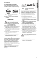
GRUNDFOS INSTRUCTIONS UP Series circulators® Installation and operating instructions UP15 and UP26 Stainless and Bronze
English (US) English (US) Installation and operating instructions Original installation and operating instructions CONTENTS Page 1. Limited warranty 2 2. Symbols used in this document 3 3. 3.1 3.2 3.3 Product description Introduction Delivery and handling Pre-installation checklist 3 3 3 3 4. 4.1 4.2 5 5 4.3 Installation Position of the terminal box How to change the terminal box position Installation requirements 5. 5.1 Electrical installation For all 115 V and 230 V models 6 6 6.
WARNING If these safety instructions are not observed, it may result in personal injury. WARNING If these instructions are not observed, it may lead to electric shock with consequent risk of serious personal injury or death. CAUTION Caution Note If these safety instructions are not observed, it may result in malfunction or damage to the equipment. Notes or instructions that make the job easier and ensure safe operation. 3. Product description 3.
English (US) 3.3.3 Inlet pressure requirements The pressure required at the inlet of the pump is a function of the temperature of the water as shown in Table B. In a pressurized system, the required inlet pressure is the minimum allowable system pressure. In a system open to the atmosphere, the required inlet pressure is the minimum distance the pump must be located below the lowest possible water level of the water source (tank, pool, etc.).
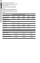
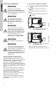
Proper installation of the pump will have the terminal box located to one side of the pump or the other, with the conduit entry down. See fig. 1. Acceptable TM05 5563 3812 Fig. 2 Fig. 1 Recommended terminal box orientation 4.2 How to change the terminal box position WARNING If the terminal box position needs to be changed, ensure that the power supply is turned off and close the isolating valves before removing the hex socket head screws. How to change terminal box position: 1.
WARNING The safe operation of this pump requires that it be grounded in accordance with the National Electrical Code and local codes or regulations. Capacitor 1 2 3 4 5 6 7 8 Green ground Neutral Line WARNING The ground conductor should be a copper conductor of at least the size of the circuit conductor supplying power to the pump. Minimum ground conductor size is 14 AWG. Connect the ground conductor to the grounding point in the terminal box and then to an acceptable ground. Fig.
Caution Do not use the pump to vent the system. Caution Do not start the pump before filling the system. Caution Never let the pump run dry. 9. Disposal This product or parts of it must be disposed of in an environmentally sound way: 1. Use the public or private waste collection service. 2. If this is not possible, contact the nearest Grundfos company or service workshop. 7.
Grundfos companies GRUNDFOS Kansas City 9300 Loiret Blvd. Lenexa, Kansas 66219 Phone: (913) 227-3400 Fax: (913) 227-3500 www.grundfos.us United Arab Emirates GRUNDFOS Gulf Distribution P.O.Box 16768 Jebel Ali Free Zone Dubai Phone: +971-4-8815-166 Fax: +971-4-8815-136 www.grundfos.uae GRUNDFOS Canada GRUNDFOS México 2941 Brighton Road Oakville, Ontario L6H 6C9 Canada Phone: +1-905 829 9533 Telefax: +1-905 829 9512 Boulevard TLC No. 15 Parque Industrial Stiva Aeropuerto C.P. 66600 Apodaca, N.L.
Grundfos companies
98357689 1119 ECM: 1274083 www.grundfos.com Trademarks displayed in this material, including but not limited to Grundfos, the Grundfos logo and “be think innovate” are registered trademarks owned by The Grundfos Group. All rights reserved. L-UP-TL-053 © 2019 Grundfos Holding A/S, all rights reserved.