
Installation and Operating Instructions
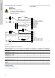
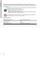
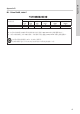
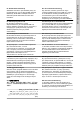
Table Of Contents

6.5 Connecting the IO connections
WARNING
Electric shock
Death or serious personal injury
‐ The IO connections of the GIM CIU
unit must be connected to SELV or
SELV-E circuits only.
1. Connect the input and output terminals according
to the drawing.
AI/DI_1
GND
AI/DI_2
GND
AI/DI_3
GND
Pt100/1000
24VDC_EXT_1 (Max. 50 mA)
24VDC_EXT_2 (Max. 50 mA)
24VDC_EXT_3 (Max. 50 mA)
DI
GND
DO_NO (Max. 30 V/500 mA)
DO_COM (Max. 30 V/500 mA)
MODBUS_D1
MODBUS_GND
MODBUS_D0
GENIbus_A
GENIbus_Y
GENIbus_B
TM076438
Wiring diagram
Options for configuration of connections
Electrical signals DI AI/DI 1 AI/DI 2 AI/DI 3 Pt100(0)
Digital input x
Analog input, 0 - 20 mA x x x
Analog input, 4 - 20 mA x x x
Analog input, 0 - 10 V x x x
Analog input, 0 - 5 V x x x
Analog input, 0.5 - 3.5 V x x x
Pt100 x
Pt1000 x
Related information
6. Electrical connection
6.2 Connecting the power supply
12
English (GB)