
Installation and Operating Instructions

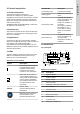
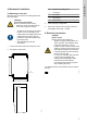
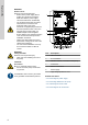
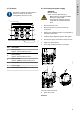
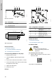
Table Of Contents

N L
21
3
TM076416
Electrical connection
Pos. Description
1 Protective earth terminal
2 Neutral terminal
3 Phase terminal
N
L
30mm (1.18”)
40mm (1.58”)
5mm
(0.20”)
5mm
(0.20”)
TM077743
Wire requirements
Related information
6. Electrical connection
6.3 Connecting GENIbus to the pump
6.5 Connecting the IO connections
6.3
Connecting GENIbus to the pump
1. Remove the front cover.
2. Lead the GENIbus cable through the cable
gland.
3. Connect the conductors to terminals A, Y and B.
4. Connect the cable screen under the earth clamp,
and tighten the earth clamp.
5. Tighten the cable gland.
6. Fit the front cover.
Example:
A
Y B
1 2 3
4
TM076415
GENIbus connection
Pos. Designation Description
1 A
GENIbus terminal A. Positive
data signal.
2 Y GENIbus terminal Y
3 B
GENIbus terminal B.
Negative data signal.
4 - Earth clamp
Related information
6. Electrical connection
6.2 Connecting the power supply
6.4
Sensor cable
WARNING
Fall hazard
Death or serious personal injury
‐ Follow local working environment
regulations.
6.4.1 Mounting the sensor cable
1. Read the GiM quick guide to see how to mount
the sensor cable.
QR99802939
net.grundfos.com/qr/i/99802939
10
English (GB)