
Installation and Operating Instructions
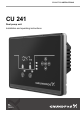

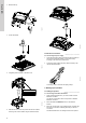
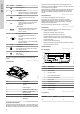
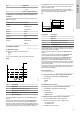
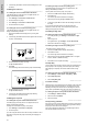
Table Of Contents
- English (GB)
- 1. General information
- 2. Installing the product
- 3. Starting up the product
- 4. Product introduction
- 5. Control functions
- 5.1 Application types
- 5.2 Setting the sensor type
- 5.3 Setting the start level
- 5.4 Setting the stop level
- 5.5 Setting the high level
- 5.6 Stop delay
- 5.7 Power-on delay
- 5.8 Dry-running protection
- 5.9 Using the same level switch for the start and stop level
- 5.10 "Multipump settings"
- 5.11 "Antiseizing"
- 5.12 Signal detection time
- 5.13 Setting the maximum number of restarts with Grundfos GO Remote
- 5.14 Motor protection
- 5.15 Alarm reset
- 5.16 Setting the buzzer with Grundfos GO Remote
- 5.17 Setting units for Grundfos GO Remote
- 5.18 Setting units for the operating panel with Grundfos GO Remote
- 5.19 GENIbus
- 5.20 Security
- 5.21 Starting the startup wizard with the operating panel
- 6. Operating the product
- 7. Servicing the product
- 8. Fault finding the product
- 8.1 Overview of alarm and warning codes
- 8.2 Code 2 (Power phase missing)
- 8.3 Code 4 (Too many motor restarts)
- 8.4 Code 9 (Power phase sequence wrong)
- 8.5 Code 12 (Service needed)
- 8.6 Code 22 (Moisture in motor of pump)
- 8.7 Code 25 (Wrong configuration)
- 8.8 Code 48 (Motor is overloaded)
- 8.9 Code 57 (Missing water in the application)
- 8.10 Code 69 (Winding temperature too high)
- 8.11 Code 84 (Memory storage media faulty)
- 8.12 Code 117 (Door opened)
- 8.13 Code 159 (Communication error CIMxxx)
- 8.14 Code 165 (Signal fault)
- 8.15 Code 191 (High water level)
- 8.16 Code 205 (Level switch inconsistency)
- 8.17 Code 225 (Communication error pump module)
- 8.18 Code 226 (Communication error IO module)
- 8.19 Code 229 (Water on floor)
- 9. Technical data
- 10. Disposing of the product

Pos. Description
1
Type
• CU 241
2 Number of pumps supported
STATUS-NOT-SET | Supported-communication-interface-modules-and-protocols-(re)-0fwnkCs.dita
4.7 Supported communication interface modules and
protocols
The following Grundfos communication interface modules can be
added to the product.
Communication interface module Protocol
CIM 050 GENIbus
CIM 150 PROFIBUS DP
CIM 200 Modbus RTU
CIM 260 3G/4G
CIM 270 GRM
CIM 280
Grundfos iSolution Cloud
(GiC)
CIM 500
Modbus TCP
PROFINET IO
GRM IP
5. Control functions
STATUS-NOT-SET | Application-types-(co)-yKqYumk.dita
5.1 Application types
You can choose between two application types:
• Empty
• Fill
You can set the application type with Grundfos GO Remote.
Empty
1
2
3
4
5
TM0713341
Pos.
Description
1 High level
2 Start level P2: start level for pump 2
3 Start level P1: start level for pump 1
4 Stop level
5 Dry-running level
The pump will start to empty the tank or pit when Start level P1 is
reached.
A second pump will start if the liquid level reaches Start level P2.
The pump stops when the liquid level is lowered to Stop level.
If the inflow of liquid exceeds the capacity of the installed pump, the
level in the tank or pit will rise. Eventually, the High level sensor will
register a high liquid level in the tank or pit. If set, the signal from
the
High level sensor can be used to activate an output relay which
can then be used to indicate a visual or acoustic alarm or send a
signal to a SCADA system.
If the pump is running and the liquid level in the tank or pit falls
below the dry-running level, the dry-running protection will stop the
pump to ensure that it is not damaged mechanically.
Fill
1
2
3
4
5
TM0713351
Designation Description
1 High level
2 Stop level
3 Start level P1: start level for pump 1
4 Start level P2: start level for pump 2
5 Dry-running level
In the filling application, the pump is installed in a tank or well from
where it pumps the liquid. The liquid is pumped into a second tank
where the level sensors are installed.
The pump will start to fill the second tank when Start level P1 is
reached.
A second pump will start if the liquid level reaches Start level P2.
The pump stops when the liquid level reaches Stop level.
If the pump for some reason does not stop at Stop level and the
liquid level keeps rising, the High level sensor will eventually
register this. If set, the signal from the High level sensor can be
used to activate a relay output which can then be used to indicate a
visual or acoustic alarm or send a signal to a SCADA system via a
communication interface.
If the pump is running and the liquid level in the tank falls below the
dry-running level, the dry-running protection will stop the pump to
ensure that it is not damaged.
Related information
6.1.2 Automatic operation
STATUS-NOT-SET | Setting-the-application-type-with-Grundfos-GO-Remote-(ta)--nryFSE.dita
5.1.1 Setting the application type with Grundfos GO Remote
1. Go to Settings > Level control > Application type.
2. Select the type.
• Empty
• Fill
5.2 Setting the sensor type
STATUS-NOT-SET | Setting-the-sensor-type-with-Grundfos-GO-Remote-(ta)-05rs6BU.dita
5.2.1 Setting the sensor type with Grundfos GO Remote
1. Go to Settings > Level control > Sensor type.
2. Select the type.
• Analog sensors
• Digital sensors
STATUS-NOT-SET | Setting-the-sensor-type-using-the-operating-panel-(ta)--ywzApI.dita
5.2.2 Setting the sensor type using the operating panel
1. Press and hold OK until S-1 or S-2 starts flashing.
2. Select the sensor type using the up or down button.
• S-1: Analog sensors
• S-2: Digital sensors.
3. Press OK to confirm the setting.
9
English (GB)