
Installation and Operating Instructions
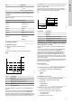
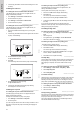
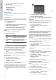
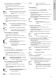
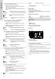
Table Of Contents
- English (GB)
- 1. General information
- 2. Installing the product
- 3. Starting up the product
- 4. Product introduction
- 5. Control functions
- 5.1 Application types
- 5.2 Setting the sensor type
- 5.3 Setting the start level
- 5.4 Setting the stop level
- 5.5 Setting the high level
- 5.6 Stop delay
- 5.7 Power-on delay
- 5.8 Dry-running protection
- 5.9 Using the same level switch for the start and stop level
- 5.10 "Multipump settings"
- 5.11 "Antiseizing"
- 5.12 Signal detection time
- 5.13 Setting the maximum number of restarts with Grundfos GO Remote
- 5.14 Motor protection
- 5.15 Alarm reset
- 5.16 Setting the buzzer with Grundfos GO Remote
- 5.17 Setting units for Grundfos GO Remote
- 5.18 Setting units for the operating panel with Grundfos GO Remote
- 5.19 GENIbus
- 5.20 Security
- 5.21 Starting the startup wizard with the operating panel
- 6. Operating the product
- 7. Servicing the product
- 8. Fault finding the product
- 8.1 Overview of alarm and warning codes
- 8.2 Code 2 (Power phase missing)
- 8.3 Code 4 (Too many motor restarts)
- 8.4 Code 9 (Power phase sequence wrong)
- 8.5 Code 12 (Service needed)
- 8.6 Code 22 (Moisture in motor of pump)
- 8.7 Code 25 (Wrong configuration)
- 8.8 Code 48 (Motor is overloaded)
- 8.9 Code 57 (Missing water in the application)
- 8.10 Code 69 (Winding temperature too high)
- 8.11 Code 84 (Memory storage media faulty)
- 8.12 Code 117 (Door opened)
- 8.13 Code 159 (Communication error CIMxxx)
- 8.14 Code 165 (Signal fault)
- 8.15 Code 191 (High water level)
- 8.16 Code 205 (Level switch inconsistency)
- 8.17 Code 225 (Communication error pump module)
- 8.18 Code 226 (Communication error IO module)
- 8.19 Code 229 (Water on floor)
- 9. Technical data
- 10. Disposing of the product

1. Switch off the power supply to the product and
other components with external supply.
2. Write down the terminal connection of each wire to ensure
correct re-connection.
3. Disconnect all wires connected to the CIM module.
4. Remove the screws that holds the module.
5. Remove the module from the control unit.
6. Fit the new module.
7. Connect all wires.
STATUS-NOT-SET | Replacing-the-battery-(ta)-0yYWEig.dita
7.4 Replacing the battery
CAUTION
Fire and chemical leakage
Minor or moderate personal injury
‐ Risk of explosion if the battery is replaced by an
incorrect type.
To replace the battery, do the following:
1. Remove the back cover.
2. Gently grab around the battery without touching it too much.
3. Pull the battery up.
4. Insert a new battery of the correct type.
Related information
9. Technical data
STATUS-NOT-SET | Fault-finding-the-product-(re)-Aecab9M.dita
8. Fault finding the product
DANGER
Electric shock
Death or serious personal injury
‐ Switch off the power supply before you start any work
on the product.
‐ Make sure that the power supply cannot be switched
on accidentally.
Fault finding and fault correction must be carried out by qualified
persons.
STATUS-NOT-SET | List-with-alarm-and-warning-codes-(re)-ywT41JQ.dita
8.1 Overview of alarm and warning codes
Code number
Description
Code 2 The power phase is missing.
Code 4 Too many motor restarts.
Code 9
The power-phase sequence is
wrong.
Code 12 Service is needed.
Code 22 Moisture in motor of pump.
Code 25 Wrong configuration.
Code 48 The motor is overloaded.
Code 57 Missing water in the application.
Code 69
The winding temperature is too
high.
Code 84
The memory-storage media is
faulty.
Code 117 The door is opened.
Code 159 Communication error CIMxxx.
Code 165 Signal fault.
Code 191 High water level.
Code number Description
Code 205 Level-switch inconsistency.
Code 225
Communication error pump
module.
Code 226
Communication error IO
module.
Code 229 Water on the floor.
STATUS-NOT-SET | Code-2-(Power-phase-missing)-(ts)-AAccPzM.dita
8.2 Code 2 (Power phase missing)
• Alarm code 2 is shown on the display.
• The alarm symbol on the display turns red and the pump
stops.
• Alarm code Power phase missing is displayed in Grundfos
GO Remote.
Cause One of the power supply phases is not
connected.
Remedy • Connect the phase.
Cause The fuse is blown somewhere on the incoming
power line.
Remedy • Replace the fuse.
STATUS-NOT-SET | Code-4-(Too-many-motor-restarts)-(ts)-AFkJ5ac.dita
8.3 Code 4 (Too many motor restarts)
• Alarm code 4 is shown on the display.
• The alarm symbol on the display turns red and the pump
stops.
• Alarm code Too many motor restarts is displayed in Grundfos
GO Remote.
Cause
The pump has been blocked or partly blocked
causing overload in the motor.
Remedy • Remove the blockage from the pump.
Related information
5.13 Setting the maximum number of restarts with Grundfos GO
Remote
STATUS-NOT-SET | Code-9-(Power-phase-sequence-wrong)-(ts)-AFvxRcE.dita
8.4 Code 9 (Power phase sequence wrong)
• Alarm code 9 is shown on the display.
• The alarm symbol on the display turns red and the pump
stops.
• Alarm code Power phase sequence wrong is displayed in
Grundfos GO Remote.
Cause
The power supply phase is set incorrectly.
Remedy • Interchange two phases.
STATUS-NOT-SET | Code-12-(Service-needed)-(ts)-ALtLiSg.dita
8.5 Code 12 (Service needed)
• Warning code 12 is shown on the display if you press
the Up or Down button.
• The warning symbol on the display turns yellow and the pump's
operating mode is unchanged.
• Warning code Service needed is displayed in Grundfos GO
Remote.
Cause
The pump requires service based on time to
next service countdown.
Remedy • Contact Grundfos or an authorised service
workshop.
• In order for the product to determine the
service time, you must have enabled the
service countdown with Grundfos GO
Remote: Settings > Service.
14
English (GB)