
Owner's Manual
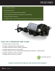


• The basic demand pump is controlled by a built-in pressure sensing demand switch.
• When a faucet or valve is opened down stream of the pump, line pressure drops thus starting the pump
automatically. Conversely, when the valve shuts, the line pressure increases turning the pump o
automatically.
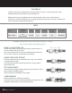
• The pressure switch actuates in response to the pump outlet pressure at a predetermined and preset
pressure. The pump label indicates the pre-set OFF pressures. Typically, the OFF pressure is accurately
set at the FACTORY and the ON pressure is within an allowable range below that value.
• In response to the characteristics of the system in which the pump is installed, such as the exibility
and length of the tubing, and the faucet or valves and the duration that they are open, these pressure
settings may vary. Therefore, changes in pressure settings is expected with use and over time.
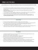
OPERATIONAL & INSTALLATION GUIDELINES
READ CAREFULLY BEFORE INSTALLING THE PUMP.
• Turn o the water.
• Cut the exible tubing in sucient length to avoid any stress on the tubing where it connects
to the pump or the tting on any accessory.
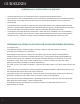
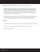
• Insert tubing into pump ports. If ttings are John Guest type, be sure tubing is inserted past the
resistance point until it bottoms out against the port stop. If compression ttings with threaded nuts
are used, insert tubing until it bottoms out in the port and hand tighten the compression nut until the
connection is tight. Then use a wrench to tighten the nut 1/2 turn clockwise or follow the wrench
tightening instructions provided by the tting manufacturer.
• The “DDP” pump is now ready for operation. Open the inlet water valve if any to allow water to ow to the
pump.
• If the power source is a transformer, plug the appropriate Aquatec supplied or approved transformer into
the receptacle and connect the pump to the transformer.
• If the power source is not a transformer, connect the pump to the appropriate power source. Open the
discharge or dispensing valve. Allow water to circulate, purging any entrapped air.
• The pump will now start building pressure. Operating pressure will vary with ow rate, ow valve, feed-
water pressure and line voltage. Check for tting leaks.
• If compression ttings with threaded nuts are used, observe any leaks after pump has run for
approximately 15 minutes
DETERMINE THE OPTIMUM LOCATION FOR YOUR PUMP BEFORE PROCEEDING.
GUIDELINES
6