PARKFIELD DESIGN + ENGINEERING GROHE GERMANY 99.0005.031/ÄM 230380/02.14 www.grohe.com 24 033 D .....1 GB F E I .....2 NL .....6 S .....7 .....3 DK .....8 .....4 .....5 N .....9 FIN ...10 PL .....11 .....16 BG .....21 CN .....26 UAE .....12 TR .....17 EST .....22 UA .....27 GR .....13 SK .....18 LV .....23 RUS .....28 CZ .....14 SLO .....19 LT .....24 H P .....15 HR .....20 RO .....
Please pass these instructions on to the end user of the fitting! S.v.
II 2
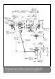
English Application Installation, see dimensional drawing on page 1. Operation is possible in conjunction with: - Pressurized storage heaters Flush piping system prior and after installation of faucet thoroughly! Operation is not possible with: - Low-pressure storage heaters (displacement water heaters) Side valves, see fig. [1]. • Valve with a groove on the top edge of the cartridge (A) and in addition marked with COLD should be mounted on the right (cold Technical data water) side. • Max.
Français Domaine d'application Montage Le service est possible en combinaison avec: Voir diagramme dimensionnel page 1. - Des chauffe-eau à accumulateur sous pression Bien rincer les canalisations avant et après l’installation! Le service n'est pas possible en combinaison avec: - Des systèmes d'eau chaude à écoulement libre Robinets d'arrêt, fig. [1]. Caractéristiques techniques • Débit maxi. 13 l/min ou 3.4 g/min / 3 bar • Pression dynamique - mini.
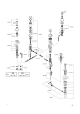
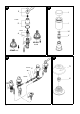
2 3 5 P 30mm H O3 O4 O1 O2 G F1 4 J I N P 36mm F F2 M P1 L K 6 8 7 R 22mm T1 T Q S1 21mm 19mm S 19mm 11mm 22mm 19mm 19mm 10mm 9 5 U R1
English Vacuum breaker, see figs. [2], [3] and [4]. 1. Insert the vacuum breaker body with seal (F) and nut (F2) through the basin hole from below, see fig. [2]. 2. Slide on seal (F1) with ring (G) and screw on nut (H). The distance from the top of the body to the bottom of the ring must be 2 3/16", see fig. [3]. 3. Secure vacuum breaker body to the basin by tightening nut (H), see fig. [2]. 4. Slide on tube (I) and cover (J), see fig. [4]. 5.
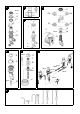
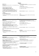
10 11 E J 17mm I D 17mm V1 A A1 V 45 883 COLD 45 882 HOT 12 13 21mm T1 X W 19mm U 7
English Maintenance Inspect and clean all parts, replace as necessary and grease with special grease. III. Check valve, see fig. [12]. Loosen nut (W) using an 21mm open-ended spanner and replace check valve (X). IV. Vertical spray, see fig. [13]. Unscrew and clean spray face plate (T1) and nozzle (U). Shut off cold and hot water supply. I. Ceramic cartridge, see fig. [10]. Secure side valve against sliding back. 1. Pull off lever (E) and unscrew escutcheon (D). 2.
D & +49 571 3989 333 impressum@grohe.de A & +43 1 68060 info-at@grohe.com AUS Argent Sydney & +(02) 8394 5800 Argent Melbourne & +(03) 9682 1231 B & +32 16 230660 info.be@grohe.com BG & +359 2 9719959 grohe-bulgaria@grohe.com CAU & +99 412 497 09 74 info-az@grohe.com CDN & +1 888 6447643 info@grohe.ca CH & +41 448777300 info@grohe.ch CN & +86 21 63758878 CY & +357 22 465200 EST & +372 6616354 grohe@grohe.ee F & +33 1 49972900 marketing-fr@grohe.