EDGE SANDER MODEL G0512 INSTRUCTION MANUAL COPYRIGHT © MAY, 2003 BY GRIZZLY INDUSTRIAL, INC. WARNING: NO PORTION OF THIS MANUAL MAY BE REPRODUCED IN ANY SHAPE OR FORM WITHOUT THE WRITTEN APPROVAL OF GRIZZLY INDUSTRIAL, INC. #528603624 PRINTED IN TAIWAN ONLINE MANUAL DISCLAIMER THE INFORMATION IN THIS MANUAL REPRESENTS THE CONFIGURATION OF THE MACHINE AS IT IS CURRENTLY BEING SHIPPED. THE MACHINE CONFIGURATION CAN CHANGE AS PRODUCT IMPROVEMENTS ARE INCORPORATED.
WARNING Some dust created by power sanding, sawing, grinding, drilling, and other construction activities contains chemicals known to the State of California to cause cancer, birth defects or other reproductive harm. Some examples of these chemicals are: • Lead from lead-based paints. • Crystalline silica from bricks, cement, and other masonry products. • Arsenic and chromium from chemically treated lumber. Your risk from these exposures varies, depending on how often you do this type of work.
TABLE OF CONTENTS SECTION 1: SAFETY........................................................................................................................2 Safety Instructions For Power Tools ..........................................................................................2 Additional Safety Instructions For Sanders ................................................................................4 SECTION 2: INTRODUCTION ..............................................................................
SECTION 1: SAFETY For Your Own Safety Read Instruction Manual Before Operating This Equipment The purpose of safety symbols is to attract your attention to possible hazardous conditions. This manual uses a series of symbols and signal words which are intended to convey the level of importance of the safety messages. The progression of symbols is described below. Remember that safety messages by themselves do not eliminate danger and are not a substitute for proper accident prevention measures.
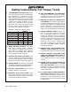
Safety Instructions For Power Tools 9. USE PROPER EXTENSION CORD. Make sure your extension cord is in good condition. Conductor size should be in accordance with the chart below. The amperage rating should be listed on the motor or tool nameplate. An undersized cord will cause a drop in line voltage resulting in loss of power and overheating. Your extension cord must also contain a ground wire and plug pin. Always repair or replace extension cords if they become damaged.
Additional Safety Instructions For Sanders • DO NOT allow anyone to stand near the sander while sanding wood stock. • NEVER leave the machine running unattended. • DO NOT jam the workpiece against the sanding belt. Firmly grasp the workpiece in both hands and ease it against the sanding belt, using light pressure. • REPLACE sanding belt when it becomes worn. • NEVER sand more than one piece of stock at a time.
SECTION 2: INTRODUCTION If you have any comments regarding this manual, please write to us at the address below: Read the manual before assembly and operation. Serious personal injury may result if safety or operational information is not understood or followed. We are proud to offer the Model G0512 Edge Sander. This Edge Sander is part of a growing Grizzly family of fine woodworking machinery.
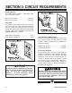
SECTION 3: CIRCUIT REQUIREMENTS Amperage Draw The Model G0512 features a 110V/220V motor that is prewired at 220V. Motor Load at 220V ..............................10 amps Motor Load at 110V ..............................20 amps Plug Type The cord set enclosed does not have a plug as the style of plug you require will depend upon the type of service you currently have or plan to install.
Grounding Extension Cords In the event of an electrical short, grounding reduces the risk of electric shock by providing a path of least resistance to disperse electric current. This tool is equipped with a power cord that has a plug with an equipment-grounding prong. The outlet must be properly installed and grounded in accordance with all local codes and ordinances. 220V Operation We do not recommend the use of extension cords on 220V equipment.
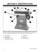
SECTION 4: IDENTIFICATION 2 1 11 10 3 9 4 5 8 6 7 Figure 3. The following is a list of controls and components on the Model G0512. Please take time to become familiar with each item and its location. These items will be used throughout the manual and knowing them is essential to understanding the instructions and terminology used in this manual. 1. 2. 3. 4. 5. 6. -8- Belt Tracking Knob Tracking Lock Contour Sanding Area Sanding Table Table Elevation Handwheel Lead Screw Lock Handle 7. 8. 9. 10.
SECTION 5: SET UP Unpacking The Model G0512 was carefully packed when it left our warehouse. If you discover the machine is damaged after you have signed for delivery, please immediately call Customer Service at (570) 546-9663 for advice. Save the containers and all packing materials for possible inspection by the carrier or its agent. Otherwise, filing a freight claim can be difficult. When you are completely satisfied with the condition of your shipment, you should inventory the contents.
Hardware Recognition Chart -10- G0512 Edge Sander
Clean Up Site Considerations The unpainted surfaces are coated with a waxy oil to protect them from corrosion during shipment. Remove this protective coating with a solvent cleaner or citrus-based degreaser such as Grizzly’s G7895 Degreaser. To clean thoroughly, some parts may need to be removed. For optimum performance from your machine, make sure you clean all moving parts or sliding contact surfaces that are coated.
Beginning Assembly This section will cover the minimum assembly and adjustment instructions needed to begin operation. For best results, complete the assembly in the order provided in this manual and then read the remaining portion of the manual before attempting any type of operations. Safety must come first! Read and follow these instructions before beginning assembly: Installing Feet To install the feet on the sander: 1. Thread the feet into the bottom of the stand as shown in Figure 5.
Installing Tension Lever Installing Sanding Belt To install the tension lever: To install the sanding belt: 1. 1. Make sure the tension lock knob is loosened. 2. Move the tension lever into the release position as shown in Figure 7. Thread the end of the tension lever into the swivel assembly as shown in Figure 6. Tension Lock Knob Tension Lever Lock Nut Swivel Assembly Figure 6. Installing tension lever in swivel assembly. 2.
Attaching Dust Port Connecting Plug to Cord To attach the dust port: 1. Attach the dust port to the support brackets with the three 5⁄16"-18 x 1⁄2" hex bolts and washers, as shown in Figure 9, but DO NOT completely tighten the bolts yet. The voltage you decide to use with your sander will determine which plug and receptacle you install. Read pages 6 & 7, in Section 3: Circuit Requirements for more information. Install the plug and receptacle now. Figure 9. Dust port attached to brackets. 2.
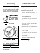
Installing Roller Guard To install the roller guard: 1. Place the guard on top of the idler roller and secure it in position with the included small star knob, as shown in Figure 10. Test Run & Tracking Before you can install the table, you must run the sander to track the belt. However, you should perform a “pre-tracking” procedure before starting the sander to ensure that the belt does not come off of or bottom out on the rollers during the initial startup. To pretrack the belt: Figure 10.
To test run and track the belt: 1. Make sure the belt is properly pre-tracked as described previously. 2. Tie back loose clothing and long hair to protect yourself from getting caught in the moving sanding belt when you start the machine. 3. Make sure the switch is in the down position (OFF), then connect the sander to the power source.
4. Install the front L support with the lock handle and two 3⁄8" flat washers as shown in Figure 14. 8. Use a 3mm or 1⁄8" Allen wrench as a gauge to position the table evenly away from the platen and the idler roller. Do this by placing the Allen wrench as shown in Figure 16, at the three locations shown in Figure 17. Figure 14. Front L support installed. 5. Install the L supports with the lock handles and remaining four 3⁄8" flat washers as shown in Figure 15.
Installing Back Stop Connecting to Dust Collection System To install the back stop: 1. Use a machinists square to position the back stop perpendicular to the platen, on the end of the table that is near the ON/OFF switch. 2. Secure the backstop to the table with three #8 x 3⁄4" Phillips head tap screws (as shown in Figure 18). The dust port can be connected to a dust collection system with a 4" hose.
SECTION 6: OPERATIONS Your safety is important! Please follow the warnings below: Operating this equipment creates the potential for flying debris to cause eye injury. Always wear safety glasses when operating equipment. Everyday glasses or reading glasses only have impact resistant lenses, they are not safety glasses. Be certain the safety glasses you wear meet the appropriate standards of the American National Standards Institute (ANSI).
Adjusting Table Height Sanding Belt Selection The table can be adjusted up or down to allow the operator to use more surface area of the sanding belt. Adjusting the height will also prevent the platen graphite and sanding belt from wearing out in one place. The Model G0512 accepts a 6" x 80" sanding belt. To adjust the table: 1. Loosen the lock handles that secure the L supports and the lead screw. 2.
Edge & End Sanding Keep loose clothing out of the way of machinery and keep hair pulled back during operations! To perform an edge or end sanding operation: 1. Make sure the vertical tracking on the sanding belt is set. 2. Start the sander by pulling the switch up. 3. Support the workpiece against the back stop, keep your fingers away from the moving belt and slowly feed the workpiece into the moving belt, as shown in Figures 23 & 24.
Contour Sanding Keep loose clothing out of the way of machinery and keep hair pulled back during operations! To perform a contour sanding operation: 1. Start the sander by pulling the switch up. 2. Grip the workpiece firmly and feed it into the curved end (as shown in Figure 25), and continue moving the workpiece profile along the contour until you achieve your desired shape. -22- Figure 25. Typical contour sanding operation.
SECTION 7: MAINTENANCE Lubrication Disconnect power to the machine when performing any adjustments or maintenance. Failure to do this may result in serious personal injury. General Regular periodic maintenance on your Grizzly Edge Sander will ensure its optimum performance. Make a habit of inspecting your sander each time you use it. Check for the following conditions and repair or replace when necessary. 1. Loose mounting bolts. 2. Worn switch. 3. Worn or damaged cords and plugs. 4.
SECTION 8: SERVICE ADJUSTMENTS Adjusting Tensioner Disconnect power to the machine when performing any adjustments or maintenance. Failure to do this may result in serious personal injury. About Service The belt tensioner is normally adjusted as the belt stretches. Two good indications of belt stretch (or a loose belt) are if the belt slaps against the platen while running or if it slips on the rollers.
6. Rotate the tension nut counter-clockwise to increase the tension and clockwise to decrease the tension. — Decreased Tension: If you rotated the tension nut clockwise, move the belt tension lever to the release position. If it is not too stiff, continue to step 7. If it is too stiff to move comfortably, then either the shaft spring tension needs to be reset, the tension shaft needs lubrication, or the idler roller-to-platen relationship needs to be adjusted (page 29-30).
5. Turn the tension nut counter-clockwise until the threads of the tension shaft are flush with the nut, as shown in Figure 37. Parallel Belt Tracking The belt should track on the rollers so that the top edge of the sanding belt stays parallel with the top edge of the platen graphite, as illustrated in Figure 38. Figure 37. Tension nut flush with threads. 6. Loosen the tracking control bolt (Figure 36, page 25). 7. Pull on the idler roller to take up the slack in the tension shaft. 8.
To adjust the parallel tracking of the sanding belt: 1. 6. Disconnect the sander from the power source! 2. Remove the dust port. 3. Remove the table by removing the lock handles, but keeping the L support brackets and elevation plate attached to the table as shown in Figure 39. Thread in the necessary two of the four parallel tracking setscrews approximately 1⁄4-1⁄2 a turn, as discussed below.
Platen-to-Rollers Adjustments 4. Now place the straightedge across the BOTTOM part of the platen graphite and the main roller as shown in Figure 42. Measure the gap, if there is one, between the straightedge and the main roller. The platen can be adjusted forward or backward in relation to the main and idler rollers. When the platen is correctly adjusted, it should extend beyond the rollers approximately 1⁄8".
2. Place the straightedge across the TOP of the platen graphite and the idler roller. Measure the gap, if there is one, between the straightedge and the main roller. 3. Place the straightedge across the BOTTOM of the platen graphite and the idler roller. Measure the gap, if there is one, between the straightedge and the main roller. — Correct Platen-to-Idler Roller Relationship: The distance between the straightedge and the idler roller is approximately 1⁄8" at both the top and bottom.
3. Loosen the two cap screws, shown in Figure 44, approximately one full turn. Figure 44. Idler roller adjustment cap screws. 4. 5. 6. 7. Place a straightedge across the TOP part of the platen graphite and in front of the idler roller, and adjust the idler roller so that it is approximately 1⁄8" away from the straightedge.
SECTION 9: REFERENCE INFO The following pages contain troubleshooting, the wiring diagram, general machine data, parts diagrams, parts lists and Warranty/Return information for your Model G0512. Aftermarket Accessories If you need parts or help in assembling your machine, or if you need operational information, call the Grizzly Service Department. Trained service technicians will be glad to help you.
MACHINE DATA SHEET Customer Service #: (570) 546-9663 • To Order Call: (800) 523-4777 • Fax #: (800) 438-5901 GRIZZLY MODEL G0512 HEAVY-DUTY EDGE SANDER Design Type ........................................................................ Expanded Table, Floor Model Overall Dimensions and Specifications: Table Size ....................................................................................................24" x 421⁄4" Overall Height (With Handle Up) ..................................................
115 G0512 Edge Sander 15 14 12 10 11 24 21 23A 36 87 46 78 20A 20 21A 94 99 108 50 52 65 66 5 64 51A 92 78A 83 81 94 26 90 54 22 29 10 78 35 30 28 33 9 116 114 4B 3 4A 78 4B 42 109 5 1 17 2 32 59 61 78 51E 4A 3 31 109A 95 51A 41 23B 25 50 34 52 27 39 94 24 37 40 43 52 52 78 50 72 58 53 56 55 94 69 74 51C 50 51B 51D 72 80 73 17 74 74 74 6 73 70 71 78 77 51D 50 49 7 8 80 75 74 17 86 111 79 112 110 113
REF PART # 1 2 3 4A 4B 5 6 7 8 9 10 11 12 14 15 17 20 20A 21 21A 22 23A 23B 24 25 26 27 28 29 30 31 32 33 34 35 36 37 39 40 41 42 43 46 49 50 51A 51B 51C P0512001 P0512002 PB16 PLW06M PW02 PSB14 P0512006 PN09 PLW10M PR08M P0512010 P0512011 P0512012 PLW10M PN04 PB09 P0512020 P0512020A PSS10 P0512021A P0512022 P0512023A P0512023B PSB03 P0512025 PB07 P0512027 P0512028 P0512029 P0512030 PN13 PN22 P0512033 PB21 PN08 P0512036 P0512037 P0512039 P0512040 P0512041 P0512042 P0512043 P0512046 P0512049 PHTEK11 P0512
Troubleshooting Machine SYMPTOM POSSIBLE CAUSE Motor will not start. 1. Low voltage. 1. Check power line for proper voltage. 2. Open circuit in motor or loose connec- 2. Inspect all lead connections on motor for loose or open connections. tions. CORRECTIVE ACTION 1. Inspect cord or plug for damaged insulation and shorted wires. Motor will not start; fuses or 1. Short circuit in line cord or plug. 2. Short circuit in motor or loose connec- 2.
Troubleshooting Sanding SYMPTOM POSSIBLE CAUSE CORRECTIVE ACTION Deep sanding grooves or 1. Sanding belt grit too coarse for the marks in workpiece. desired finish. 2. Workpiece is being sanded across the grain. 3. Too much sanding force on workpiece. 4. Workpiece held still against the belt. 1. Use a finer grit sanding belt. 2. Sand with the grain. 3. Reduce pressure on workpiece while sanding. 4. Keep workpiece moving while sanding on the belt. Grains easily rub off the 1.
G0512 Wiring Diagram NOTE: THE WIRES FROM THE POWER SUPPLY, EXCEPT THE GREEN GROUND WIRE, ARE INTERCHANGABLE, THEREFORE COLORS ARE NOT SPECIFIED. Disconnect power from machine before performing any electrical service. Failure to do this will result in a shock hazard, leading to injury or death. 110 VOLT MOTOR WIRES BLACK YELLOW WHITE RED GREEN (GROUND) TO 110 VOLT POWER SUPPLY 220VOLT MOTOR WIRES BLACK RED Model G0512 Copyright © May, 2003. Grizzly Industrial, Inc.
Warranty and Returns Grizzly Industrial, Inc. warrants every product it sells for a period of 1 year to the original purchaser from the date of purchase. This warranty does not apply to defects due directly or indirectly to misuse, abuse, negligence, accidents, repairs or alterations or lack of maintenance.
WARRANTY CARD Name ____________________________________________________________________________________ Street ____________________________________________________________________________________ City ______________________________________________________________State________Zip_________ Phone Number_______________________E-Mail_______________________FAX________________________ MODEL # G0512 Edge Sander Serial # _________________________ Order #______________________ The following information is given on a
FOLD ALONG DOTTED LINE Place Stamp Here GRIZZLY INDUSTRIAL, INC. P.O.
"UY $IRECT AND 3AVE WITH 'RIZZLY® n 4RUSTED 0ROVEN AND A 'REAT 6ALUE 6ISIT /UR 7EBSITE 4ODAY !ND $ISCOVER 7HY 'RIZZLY§ )S 4HE )NDUSTRY ,EADER s 3%#52/$).' s /2$%3()04.7 5 s %-!),230/.