MODEL G0459/G0459P 12" DRUM SANDER OWNER’S MANUAL 177335 Copyright © October, 2005 By Grizzly Industrial, Inc. Revised JULY, 2011 (BL) Warning: No portion of this manual may be reproduced in any shape Or form without the written approval of Grizzly Industrial, inc.
This manual provides critical safety instructions on the proper setup, operation, maintenance, and service of this machine/tool. Save this document, refer to it often, and use it to instruct other operators. Failure to read, understand and follow the instructions in this manual may result in fire or serious personal injury—including amputation, electrocution, or death. The owner of this machine/tool is solely responsible for its safe use.
Table of Contents INTRODUCTION................................................ 2 Manual Accuracy............................................ 2 Contact Info.................................................... 2 Machine Description....................................... 2 Identification.................................................... 3 Machine Data Sheet....................................... 4 SECTION 1: SAFETY........................................ 8 Safety Instructions for Machinery...................
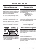
INTRODUCTION Manual Accuracy Contact Info We are proud to offer this manual with your new machine! We've made every effort to be exact with the instructions, specifications, drawings, and photographs of the machine we used when writing this manual. However, sometimes errors do happen and we apologize for them. We stand behind our machines. If you have any service questions, parts requests or general questions about the machine, please call or write us at the location listed below.
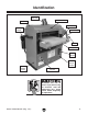
Identification Dust Port Top Cover Cover Lock Knob Depth Scale DC Feed Motor Crank Handle Handle Conveyor Belt On/Off Switch Drum Sander Frame Thermal Circuit Breaker Variable Speed Control Figure 1. Front view, Model G0459. To reduce the risk of serious injury when using this machine, read and understand this entire manual before beginning any operations. Model G0459/G0459P (Mfg.
0$&+,1( '$7$ 6+((7 Customer Service #: (570) 546-9663 · To Order Call: (800) 523-4777 · Fax #: (800) 438-5901 02'(/ * %$%< '580 6$1'(5 Product Dimensions: Weight.............................................................................................................................................................. 139 lbs. Width (side-to-side) x Depth (front-to-back) x Height........................................................................... 27 x 24 x 27 in. Footprint (Length x Width)..
Main Specifications: Operation Information No Of Sanding Heads....................................................................................................................................... 1 Maximum Board Width.............................................................................................................................. 12 in. Minimum Board Width................................................................................................................................. 2 in.
0$&+,1( '$7$ 6+((7 Customer Service #: (570) 546-9663 · To Order Call: (800) 523-4777 · Fax #: (800) 438-5901 02'(/ * 3 %$%< '580 6$1'(5 32/$5 %($5 6(5,(6 Product Dimensions: Weight.............................................................................................................................................................. 139 lbs. Width (side-to-side) x Depth (front-to-back) x Height........................................................................... 27 x 24 x 27 in.
Main Specifications: Operation Information No Of Sanding Heads....................................................................................................................................... 1 Maximum Board Width.............................................................................................................................. 12 in. Minimum Board Width................................................................................................................................. 2 in.
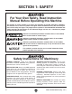
SECTION 1: SAFETY For Your Own Safety, Read Instruction Manual Before Operating this Machine The purpose of safety symbols is to attract your attention to possible hazardous conditions. This manual uses a series of symbols and signal words intended to convey the level of importance of the safety messages. The progression of symbols is described below. Remember that safety messages by themselves do not eliminate danger and are not a substitute for proper accident prevention measures.
DISCONNECTING POWER SUPPLY. 6alVnh Y^h" XdccZXi bVX]^cZ [gdb edlZg hjeean WZ[dgZ hZg" k^X^c\! VY_jhi^c\! dg X]Vc\^c\ Xjii^c\ iddah W^ih! WaVYZh! XjiiZgh! ZiX# # BV`Z hjgZ hl^iX] ^h ^c D;; edh^i^dc WZ[dgZ gZXdccZXi^c\ id Vkd^Y Vc jcZmeZXi" ZY dg jc^ciZci^dcVa hiVgi# APPROVED OPERATION.
Additional Safety for Drum Sanders FEEDING STOCK. Do not stand in the direct path of a workpiece at the infeed end when feeding your stock. Never sand more than one piece of stock at a time. DO NOT jam the workpiece into the machine during operation. Firmly grasp the workpiece in both hands and ease it into the machine using light pressure. MINIMUM STOCK DIMENSIONS. Do not sand any stock thinner than 1⁄ 8", narrower than 2", or shorter than 8".
SECTION 2: POWER SUPPLY Availability Circuit Requirements 7Z[dgZ ^chiVaa^c\ i]Z bVX]^cZ! Xdch^YZg i]Z VkV^a" VW^a^in VcY egdm^b^in d[ i]Z gZfj^gZY edlZg hjeean X^gXj^i# >[ Vc Zm^hi^c\ X^gXj^i YdZh cdi bZZi i]Z gZfj^gZbZcih [dg i]^h bVX]^cZ! V cZl X^gXj^i bjhi WZ ^chiVaaZY# Id b^c^b^oZ i]Z g^h` d[ ZaZXigdXj" i^dc! [^gZ! dg Zfj^ebZci YVbV\Z! ^chiVaaVi^dc ldg` VcY ZaZXig^XVa l^g^c\ bjhi WZ YdcZ Wn V fjVa^[^ZY ZaZXig^X^Vc ^c VXXdgYVcXZ l^i] Vaa Veea^XVWaZ XdYZh VcY hiVcYVgYh# I]^h bVX]^
Grounding & Plug Requirements I]^h bVX]^cZ BJHI WZ \gdjcYZY# >c i]Z ZkZci d[ XZgiV^c bVa[jcXi^dch dg WgZV`Ydlch! \gdjcY^c\ gZYjXZh i]Z g^h` d[ ZaZXig^X h]dX` Wn egdk^Y^c\ V eVi] d[ aZVhi gZh^hiVcXZ [dg ZaZXig^X XjggZci# I]^h bVX]^cZ ^h Zfj^eeZY l^i] V edlZg XdgY i]Vi ]Vh Vc Zfj^ebZci"\gdjcY^c\ l^gZ VcY V \gdjcY" ^c\ eaj\ h^b^aVg id i]Z [^\jgZ WZadl # I]Z eaj\ bjhi dcan WZ ^chZgiZY ^cid V bViX]^c\ gZXZeiVXaZ djiaZi i]Vi ^h egdeZgan ^chiVaaZY VcY \gdjcYZY ^c VXXdgYVcXZ l^i] Va
SECTION 3: SETUP Unpacking This machine presents serious injury hazards to untrained users. Read through this entire manual to become familiar with the controls and operations before starting the machine! Ndjg bVX]^cZ lVh XVgZ[jaan eVX`V\ZY [dg hV[Z igVchedgiVi^dc# GZbdkZ i]Z eVX`V\^c\ bViZg^Vah [gdb VgdjcY ndjg bVX]^cZ VcY ^cheZXi ^i# >[ ndj Y^hXdkZg Vcn YVbV\Z! please call us immediately at (570) 546-9663 for advice.
Site Considerations Weight Load Physical Environment GZ[Zg id i]Z Machine Data Sheet [dg i]Z lZ^\]i d[ ndjg bVX]^cZ# BV`Z hjgZ i]Vi i]Z hjg[VXZ jedc l]^X] i]Z bVX]^cZ ^h eaVXZY l^aa WZVg i]Z lZ^\]i d[ i]Z bVX]^cZ! VYY^i^dcVa Zfj^ebZci i]Vi bVn WZ ^chiVaaZY dc i]Z bVX]^cZ! VcY i]Z ]ZVk^Zhi ldg`" e^ZXZ i]Vi l^aa WZ jhZY# 6YY^i^dcVaan! Xdch^YZg i]Z lZ^\]i d[ i]Z deZgVidg VcY Vcn YncVb^X adVY^c\ i]Vi bVn dXXjg l]Zc deZgVi^c\ i]Z bVX]^cZ# I]Z e]nh^XVa Zck^gdcbZci l]ZgZ ndjg bVX]^cZ ^h deZg
Mounting The base of this machine has holes that allow it to be mounted to a workbench. We strongly recommend that you mount your machine to a workbench to prevent it from moving during operation. An unexpected movement could result in an injury or property damage. The strongest mounting option is a "Through Mount" where holes are drilled all the way through the workbench, and hex bolts, washers, and hex nuts are used to secure the drum sander to the workbench.
Dust Collection DO NOT operate the Model G0459/G0459P without an adequate dust collection system. This sander creates substantial amounts of wood dust while operating. Failure to use a dust collection system can result in short and long-term respiratory illness. Recommended CFM at Dust Port: 150 CFM Do not confuse this CFM recommendation with the rating of the dust collector.
Test Run Recommended Adjustments Once the assembly is complete, test run your machine to make sure it runs properly. If, during the test run, you cannot easily locate the source of an unusual noise or vibration, stop using the machine immediately, then review the Troubleshooting on Manual Page 23. For your convenience, the adjustments listed below have been performed at the factory and no further setup is required to operate your machine.
SECTION 4: OPERATIONS Operation Overview I]Z ejgedhZ d[ i]^h dkZgk^Zl ^h id egdk^YZ i]Z cdk" ^XZ bVX]^cZ deZgVidg l^i] V WVh^X jcYZghiVcY^c\ d[ ]dl i]Z bVX]^cZ ^h jhZY Yjg^c\ deZgVi^dc! hd i]Z bVX]^cZ Xdcigdah$XdbedcZcih Y^hXjhhZY aViZg ^c i]^h bVcjVa VgZ ZVh^Zg id jcYZghiVcY# 9jZ id i]Z \ZcZg^X cVijgZ d[ i]^h dkZgk^Zl! ^i ^h not ^ciZcYZY id WZ Vc ^chigjXi^dcVa \j^YZ# Id aZVgc bdgZ VWdji heZX^[^X deZgVi^dch! gZVY i]^h Zci^gZ bVcjVa VcY hZZ` VYY^i^dcVa igV^c^c\ [gdb ZmeZ" g^ZcXZY
Basic Controls Refer to Figure 11 and the following descriptions to become familiar with the basic controls of this machine. A. Variable Speed Knob: Adjusts feed rate from 2.47–17.3 FPM. Rotate clockwise to increase feed speed, rotate counterclockwise to decrease feed speed. B. Hand Crank: Used to raise or lower the conveyor table to control depth of cut. Each full rotation of the hand crank raises or lowers the conveyor table approximately 0.027" (0.69 mm).
Sanding Tips • Replace the sandpaper with a higher grit to achieve a finer finish. • Raise the table with a maximum of ⁄4 turn of the crank handle until the workpiece is the desired thickness. 1 Stock Inspection and Requirements Some workpieces are not safe or may require modification before they are safe to sand.
Depth of Cut The optimum depth of cut will vary based on the type of wood, feed rate, and sandpaper grit. Under most sanding conditions, the depth should not exceed 0.006" (0.15 mm) (approx. 1⁄4 turn of the handwheel). Each full turn of the crank handle raises the conveyor table approximately 0.027" (0.69 mm). Attempts to remove too much material can cause jamming, wood burning, rapid paper wear or tearing, poor finish, belt slippage, and motor damage. To set the depth of cut: 1.
Variable Speed The variable speed knob allows you to increase the feed rate from 2.47–17.3 FPM. The correct speed to use depends on the type of stock you are using (hardwood vs. softwood) and the stage of finish you are at with that workpiece. As a general rule, a slower feed rate sands the surface smoother, but runs the risk of burning the wood; a faster feed rate removes material faster, but runs the risk of overloading the motor.
Choosing Sandpaper There are many types of sanding belts to choose from. We recommend aluminum oxide for general workshop environments. Below is a chart that groups abrasives into different classes, and shows which grits fall into each class. Grit Class 36 Extra Coarse Rough sawn boards, thickness sanding, and glue removal. &' ($) Usage 60 Coarse Thickness sanding and glue removal. 80–100 Medium Removing planer marks and initial finish sanding. 120–180 Fine 4.
SECTION 5: ACCESSORIES Some aftermarket accessories can be installed on this machine that could cause it to function improperly, increasing the risk of serious personal injury. To minimize this risk, only install accessories recommended for this machine by Grizzly. NOTICE Refer to the newest copy of the Grizzly Catalog for other accessories available for this machine. Aluminum Oxide Hook & Loop Sanding Rolls, 3" x 50' H4422—60 Grit: Use for thickness sanding and glue removal.
SECTION 6: MAINTENANCE Lubrication Always disconnect power to the machine before performing maintenance. Failure to do this may result in serious personal injury. Schedule For optimum performance from your machine, follow this maintenance schedule and refer to any specific instructions given in this section. Daily Check: • Loose mounting bolts. • Worn switch. • Worn or damaged cords or plugs. • Damaged V-belt. • Any other unsafe condition.
Pillow Block Bearings These must be lubricated every 20 hours of operation. Use a grease gun to pump one or two shots of a high-quality grease into each grease fitting (Figure 22), located on the top of each pillow block bearing. Failure to routinely inspect your drum sander for damage and wear could result in unsatisfactory work results, premature component or machinery failure, or operator injury. We recommend you create a checklist for routine inspection and maintenance.
SECTION 7: SERVICE GZk^Zl i]Z igdjWaZh]ddi^c\ VcY egdXZYjgZh ^c i]^h hZXi^dc ^[ V egdWaZb YZkZadeh l^i] ndjg bVX]^cZ# >[ ndj cZZY gZeaVXZbZci eVgih dg VYY^i^dcVa ]Zae l^i] V egdXZYjgZ! XVaa djg IZX]c^XVa Hjeedgi Vi *,% *)+".++(# Note: Please gather the serial number and manufacture date of your machine before calling. Troubleshooting Motor & Electrical Symptom Possible Cause Possible Solution Machine does not 1. Plug or receptacle is at fault or wired 1.
Sanding Operations Symptom Possible Cause Possible Solution 1. Seal all leaks, size ducts correctly, eliminate bends, and refer to Dust Collection Basics Handbook (ISBN 0-9635821-2-7) for further recommendations. 2. Make sure all hot lines and grounds are operational and have correct voltage on all legs. 3. Replace bad belt, align pulleys, and re-tension. 4. Correct motor wiring (see Page 45). 5. Test power plug and receptacle for good contact and correct wiring. 6. Replace loose pulley and shaft. 7.
Symptom Shor t lifespan. Conveyor under load. Possible Cause V- belt 1. Pulleys not aligned correctly. 2. Improperly tensioned. slips 1. Conveyor is too loose. 2. Too much load. Conveyor tracks to 1. Conveyor tracking is incorrect. one side; conveyor hits the roller cover. Possible Solution 1. Align pulleys (Page 31). 2. Properly tension V-belts (Page 30). 1. Tension conveyor (Page 32). 2. Decrease load. 1. Track the conveyor so it runs straight (Page 32). Workpiece pulls 1.
Gauge Blocks V-Belt Service Tools Needed: Qty 6' Long 2x4......................................................... 1 Miter Saw (or Circular Saw)................................ 1 Jointer................................................................. 1 Table Saw........................................................... 1 Tools Needed: Qty Hex Wrench 6mm............................................... 1 Wrench 12mm.................................................... 1 Straightedge........................
Pulley Alignment To adjust V-belt tension: 1. DISCONNECT POWER TO THE SANDER! 2. Open the rear panel. 3. Loosen the motor mount bolts and raise or lower the motor bracket, as shown in Figure 26, to loosen or tighten the V-belt. 4. Tighten the motor mount bolts and replace the rear panel. Pulley alignment is another important factor in power transmission and belt life. The pulleys should be parallel to each other and in the same plane (coplaner) for optimum performance.
Conveyor Tensioning & Tracking 2. Turn both of the conveyor adjustment bolts counterclockwise one full turn at a time until the conveyor belt no longer slips during operation. —If the conveyor starts tracking to one side, immediately turn the drum sander OFF and perform the tracking instructions. Tools Needed: Qty Wrench 19mm.................................................... 1 Phillips Head Screwdriver #2.............................
Drum Adjustments Tools Needed: Qty Hex Wrench 4mm............................................... 1 Wrench 19mm.................................................... 1 Wrench 10mm.................................................... 1 Socket 14mm...................................................... 1 Measuring Tape.................................................. 1 Gauge Blocks (see Page 30)............................. 2 Feeler Gauge Set...............................................
6. Lower the table one full turn of the crank handle. Wait until the chain starts moving before starting to count the crank handle rotation. To adjust the sanding drum perpendicular to the feed direction (Figure 32): 7. Starting at one end, place a 0.002" feeler gauge between the sanding drum and the gauge block. (The feeler gauge should slide with moderate resistance, without forcing the drum to roll.) HVcY^c\ 9gjb .%ß 8. Repeat Step 7 at the other end of the drum.
Pressure Roller Height Tools Needed: Qty Wrenches/Sockets 10mm................................... 1 Gauge Blocks (see Page 30)............................. 2 Factory Setting: Distance Below Sanding Drum.......0.080" (2mm) The pressure rollers are factory set at 0.080" (2mm) below the bottom of the sanding drum and are fully adjustable either up/down with the four lower adjustment bolts (Figure 34). After the adjustment has been made, always lock the jam nuts against the bottom to prevent them from moving.
5. Turn the crank handle three full rotations (counting from the point of actual table movement so handwheel freeplay does not affect your count) to lower the table so the gauge blocks are below the pressure rollers, as shown in Figure 36. Figure 37. Pressure rollers set correct distance below bottom of sanding drum. 9. Tighten the jam nuts (Figure 34) to lock the adjustment. Figure 36. Gauge blocks below pressure rollers.
Table Lift Screws Tools Needed: Qty Hex Wrench 6mm............................................... 1 Wrench/Socket 12mm........................................ 1 Chalk, Correction Fluid, or Paint........................ 1 Phillips Head Screwdriver #2............................. 1 Flat Head Screwdriver........................................ 1 The table lift screws are connected by a chain and driven by the crank handle.
Conveyor Belt Replacement Tools Needed: Qty Hex Wrench 6mm............................................... 1 Wrench/Socket 19mm........................................ 1 Wrenches/Sockets 14mm................................... 2 Wrench/Socket 12mm........................................ 1 Wrench 10mm.................................................... 1 Phillips Head Screwdriver #2............................. 1 Measuring Tape.................................................. 1 Gauge Blocks (see Page 30)....
6. Remove the rear pressure roller (4 hex bolts and 4 flat washers) along with the brackets, compression springs, and spring plates shown in Figure 42. 9. Remove the sanding drum (4 lock nuts and 4 flat washers) and V-belt (Figure 44). Spring Plate Compression Spring Bracket NEW PHOTO Figure 42. Rear pressure roller components. 7. Remove the rear panel. 8. Loosen the hex bolts securing the motor bracket to the frame, raise the motor and remove the V-belt from the motor pulley (see Page 31 for help).
11. Mark the top of the table lift screws with arrows (all pointing in same direction) and mark the screws with liquid correction fluid above the mounting bracket (Figure 46). Later, when you reassemble the conveyor table, you can use these marks to reset the table height close to the current position. 15. Disconnect the conveyor feed motor wires from the circuit board. 16. Remove the scale pointer.
18. Lay the conveyor table on the edge of a workbench so the conveyor motor can hang freely. 19. Remove the conveyor motor (4 cap screws) from the conveyor motor cover, and remove the conveyor motor cover from left rear roller bracket (3 cap screws and 3 flat washers). IVWaZ 8Ve HXgZlh ;aVi LVh]Zg ;aVi LVh]Zg 8Ve HXgZl AZ[i GZVg GdaaZg 7gVX`Zi 8Ve HXgZl 8dckZndg Bdidg 8dkZg 8dckZndg Bdidg Figure 50. Removing conveyor motor and rear roller bracket (not all components shown for clarity). 20.
33. Before reinstalling the gear box cover, try raising and lowering the conveyor table with the crank handle. If the helical gears (see Figure 52) are not engaged, the crank handle will only raise the table. Changing Motor Brushes If this happens, loosen the crank handle mounting bolts, and move the helical gear around until the teeth mesh with the helical crank handle gear, then secure the crank handle. Tools Needed: Qty Flat Head Screwdriver........................................
machine SECTION 8: WIRING I]ZhZ eV\Zh VgZ XjggZci Vi i]Z i^bZ d[ eg^ci^c\# =dlZkZg! ^c i]Z he^g^i d[ ^begdkZbZci! lZ bVn bV`Z X]Vc\" Zh id i]Z ZaZXig^XVa hnhiZbh d[ [jijgZ bVX]^cZh# 8dbeVgZ i]Z bVcj[VXijgZ YViZ d[ ndjg bVX]^cZ id i]Z dcZ hiViZY ^c i]^h bVcjVa! VcY hijYn i]^h hZXi^dc XVgZ[jaan# >[ i]ZgZ VgZ Y^[[ZgZcXZh WZilZZc ndjg bVX]^cZ VcY l]Vi ^h h]dlc ^c i]^h hZXi^dc! XVaa IZX]c^XVa Hjeedgi Vi *,% *)+".
Electrical Components Figure 54. Feed motor. Figure 57. Capacitor. Figure 55. Drum motor wiring. Figure 58. Variable speed control and circuit board. Figure 56. Switch box wiring. -44- READ ELECTRICAL SAFETY ON PAGE 43! Model G0459/G0459P (Mfg.
Wiring Diagram FEED MOTOR (Figure 54) ON/OFF SWITCH (Figure 56) CD 98 CIRCUIT BOARD (Figure 58) ;;D THERMAL CIRCUIT BREAKER
SECTION 9: PARTS Frame '. &% &) ''* '. &)"& '&& )) &%& &'"' &&, &&&%( &%) &%, &' '. &%- -", -") &&% &&. &&. &&( &'"& &%. && '. &&* '. + -", ,"& &+K' . '%K' (&"& '. )) (&K' )* '%")K' &%% ('K( *)"& '** *) ''( ) ') &() '. )% () )% () '' '' ') &(* &(+ &() &(* &(+ ,"' ' '%"& '&'K( '%. &('%."& *, '. &(' ,"& ,"' '. ( &() + -", + -", '' ') &() &(( &(* -"+ + -", &, &, &&. -", -"& &&'K' ) '%"+ '%"' '%"* '%"( -"& -"' -", -"& ..
Frame Parts List REF PART # DESCRIPTION REF PART # DESCRIPTION 1 2 3 4 4 5 5-1 6 7-1 7-2 8-1 8-2 8-3 8-4 8-5 8-6 8-7 9 10 10 11 12 12-1 12-2 13 14 14 14-1 15 15 16V2 16V2 17 18 19 20V2 20-1 20-2 20-3 20-4V2 20-5 20-6 20-7 22 24 28 29 30-1V2 30-2V2 30-3V2 30-4V2 30-5 31V2 31-1 32V3 P0459001 PN02 PW07 P0459004 P0459P004 P0459005 PCAP09 P0459006 P0459007-1 P0459007-2 P0459008-1 P0459008-2 P0459008-3 P0459008-4 PK06M P0459008-6 PW01 P0459009 P0459010 P0459P010 P0459011 P0459012 PS41 PN12 G2977 P0459014 P
Drum 23 25 89 89-1 90 89-1 89 26 86 86 85 27 74 17 82 81 94 25 89-1 90 89-1 73 89 42 26 70 88 74 23 89 88 85 88 71 74 73 73 70 86 88 98 74 73 85 86 85 92-1 81 82 27 92 REF PART # DESCRIPTION REF PART # DESCRIPTION 17 23 25 26 27 42 70 71 73 74 81 SET SCREW 1/4-20 X 3/8 HEX BOLT 1/4-20 X 5/8 HEX NUT 1/4-20 SPRING PLATE ADJUST PLATE KEY 5 X 5 X 20 PRESSURE ROLLER SANDING DRUM EXT RETAINING RING 19MM BUSHING PILLOW BLOCK BEARING 82 85 86 88 89 89-1 90 92 92-1 94 98
Conveyor *' ++ *, ,. ,) -% ,, *%"' *- *, (* (+ &, (* &', +) +*"& +& +. +% *&"&K' '* +) ,) +% +& *%"& *&"(K' *&K' *, &'* +) (* ,&') *&"'K) +*K( &%' &'+ +) &'* *,+ ,+ &', ,+( -( &'( *%"& (-K' (.K) (.K)"&% (.K)"&* (.K)"&+ (.K)"&( (.K)"&) (.K)"&& (.K)"& (.K)"' (.K)"&) (.K)"&' (.K)"&( (.K)". (.K)"( (.K)") (.K)"+ (.K)", (.K)", (.K)"* (.K)"* Model G0459/G0459P (Mfg. 7/11+) (.
Conveyor Parts List REF PART # DESCRIPTION REF PART # DESCRIPTION 17 25 35 36 38V2 39V4 39V4-1 39V4-2 39V4-3 39V4-4 39V4-5 39V4-6 39V4-7 39V4-8 39V4-9 39V4-10 39V4-11 39V4-12 39V4-13 39V4-14 39V4-15 39V4-16 50-1 50-2 51V2 51-1V2 PSS03 PN05 PN03 P0459036 P0459038V2 P0459039V4 PS56M PLW02M P0459039V4-3 P0459039V4-4 P6003ZZ P0459039V4-6 P6000ZZ PR06M P0459039V4-9 P0459039V4-10 P0459039V4-11 P0459039V4-12 P0459039V4-13 P0459039V4-14 P0459039V4-15 PS19M P0459050-1 P0459050-2 P0459051V2 P0459051-1V2 SET S
WARRANTY CARD CVbZ TTTTTTTTTTTTTTTTTTTTTTTTTTTTTTTTTTTTTTTTTTTTTTTTTTTTTTTTTTTTTTTTTTTTTTTTTTTTT HigZZi TTTTTTTTTTTTTTTTTTTTTTTTTTTTTTTTTTTTTTTTTTTTTTTTTTTTTTTTTTTTTTTTTTTTTTTTTTTTT 8^in TTTTTTTTTTTTTTTTTTTTTTT HiViZ TTTTTTTTTTTTTTTTTTTTTTTTT O^e TTTTTTTTTTTTTTTTTTTTT E]dcZ TTTTTTTTTTTTTTTTTTTT :bV^a TTTTTTTTTTTTTTTTTTTTTTTT >ckd^XZ TTTTTTTTTTTTTTTTT BdYZa TTTTTTTTTTTTTTTTTTTT DgYZg TTTTTTTTTTTTTTTTTTTTTTT HZg^Va TTTTTTTTTTTTTTTTTT The following information is given on a voluntary basis.
;DA9 6ADC< 9DII:9 A>C: EaVXZ HiVbe =ZgZ '2)::,9 ).$5342)!, ).# 0 / "/8 "%,,).
WARRANTY AND RETURNS 7!22!.49 !.$ 2%452.
Buy Direct and Save with Grizzly ® – Trusted, Proven and a Great Value! ~Since 1983~ Visit Our Website Today For Current Specials! ORDER 24 HOURS A DAY! 1-800-523-4777