MODEL G9298/G9299/G9300 HORIZONTAL/VERTICAL ROTARY TABLE OWNER'S Manual Copyright © MARCH, 2009 By Grizzly Industrial, Inc. Warning: No portion of this manual may be reproduced in any shape Or form without the written approval of Grizzly Industrial, inc.
This manual provides critical safety instructions on the proper setup, operation, maintenance and service of this machine/equipment. Failure to read, understand and follow the instructions given in this manual may result in serious personal injury, including amputation, electrocution or death. The owner of this machine/equipment is solely responsible for its safe use.
Table of Contents INTRODUCTION................................................................................................................................ 2 Manual Accuracy......................................................................................................................... 2 Contact Info................................................................................................................................. 2 Functional Overview.................................................
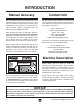
INTRODUCTION Manual Accuracy Contact Info We are proud to offer this manual with your new machine! We've made every effort to be exact with the instructions, specifications, drawings, and photographs of the machine we used when writing this manual. However, sometimes errors do happen and we apologize for them. We stand behind our machines. If you have any service questions, parts requests or general questions about the machine, please call or write us at the location listed below.
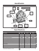
Identification Rotary Table Lock Horizontal Mounting Slot Oil Port Table Scale Backlash Adjustment Ring Rotary Table Lock Handwheel Scale Spindle Vernier Scale Backlash Adjustment Lock Vertical Mounting Holes Figure 1. Model G9289/G9299/G9300 identification. Specifications Description G9298 G9299 G9300 Clamping Surface Flatness (Concave) 0.0006" 0.0006" 0.0006" Cylindrical Center Bore Concentricity 0.0008" 0.0008" 0.0008" Taper Center Bore Concentricity 0.0008" 0.0008" 0.
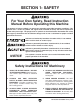
SECTION 1: SAFETY For Your Own Safety, Read Instruction Manual Before Operating this Machine The purpose of safety symbols is to attract your attention to possible hazardous conditions. This manual uses a series of symbols and signal words intended to convey the level of importance of the safety messages. The progression of symbols is described below. Remember that safety messages by themselves do not eliminate danger and are not a substitute for proper accident prevention measures.
Safety Instructions for Machinery 7. ONLY ALLOW TRAINED AND PROPERLY SUPERVISED PERSONNEL TO OPERATE MACHINERY. Make sure operation instructions are safe and clearly understood. 8. KEEP CHILDREN AND VISITORS AWAY. Keep all children and visitors a safe distance from the work area. 9. MAKE WORKSHOP CHILDPROOF. Use padlocks, master switches, and remove start switch keys. 10. NEVER LEAVE WHEN MACHINE IS RUNNING.
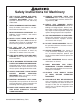
SECTION 2: SETUP Needed for Setup Read through this entire manual to become familiar with the controls and operations before using this rotary table. Follow all of the safety instructions in the owner's manual for your mill. Wear safety glasses during the entire setup process! Description Qty • Safety Glasses............................................ 1 • Cleaner/Degreaser (Page 7)....... As Needed • Disposable Shop Rags................ As Needed • Additional People........................
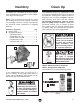
Inventory Clean Up The following is a description of the main components shipped with your machine. Lay the components out to inventory them. The unpainted surfaces are coated with a waxy oil to prevent corrosion during shipment. Remove this protective coating with a solvent cleaner or degreaser, such as shown in Figure 3. For thorough cleaning, some parts must be removed. For optimum performance, clean all moving parts or sliding contact surfaces.
Installation Before installing your rotary table, make sure that your mill table and spindle are properly aligned as instructed in your mill's owner manual. Also, remove any burrs or scratches from the mating surfaces of the mill and rotary tables by “stoning” them, then thoroughly wipe them clean and dry (refer to the Surface Care subsection on Page 18 for detailed instructions). Horizontal Position 1. DISCONNECT MILL FROM POWER! 2.
Spindle Alignment Whether the rotary table is mounted horizontally or vertically, you must align the centers of the rotary table and mill spindle to achieve quality results. There are many ways to align the rotary table, and it is up to the machinist and his capabilities to decide which approach is best. Horizontal Position Alignment 3. Turn the mill spindle so that the test indicator is aligned to the X-axis of the mill table. Note: For best results, turn the mill spindle in only one direction. 4.
6. Move the mill table along the X-axis to the position calculated in Step 5. 7. Repeat these steps with the mill table Y-axis. To center the rotary table with the mill spindle: 1. Note: Use the pattern illustrated in Figure 5 to aid in positioning the edge finder for the above procedure. Fully seat a lathe center into the rotary table spindle. Note: Any runout of the center will have to be determined and accounted for in the following steps. 2.
SECTION 3: OPERATIONS Basic Controls To reduce the risk of serious injury when using this machine, read and understand this entire manual before beginning any operations. Use Figure 7 and the following descriptions to become familiar with the basic controls of your rotary table. E D C Damage to your eyes and lungs could result from using this machine without proper protective gear. Always wear safety glasses and a respirator when operating this machine. A B D H G F Figure 7.
E. Table Scale: Displays the amount of table rotation in whole degrees. F. Spindle: Holds a center to support a workpiece for dividing work. Also, used in rotary table alignment with the mill spindle. G. Backlash Adjustment Lock: Secures the backlash adjustment ring in place. 2. Loosen the screw on the back of the vernier scale and rotate so that the zero mark is in a good viewing position, then re-tighten the screw. 3.
2. Slowly continue to turn the handwheel clockwise to 42' as displayed on the handwheel scale (see the illustration in Figure 9). In the following two exercises, it is assumed that the following statements are true before beginning the operation: 20 Arc Seconds 60 40 30 20 10 Degree 1 0 50 40 Basic Operation Vernier Scale 30 20 10 0 50 Handwheel Scale 42 Arc Minutes Figure 9. Table set at 16° 42' 20". 3.
To make five evenly spaced holes: To make two circular slots: 1. Use the handwheel to rotate the rotary table to the zero mark on the table scale, then tighten both table locks. 1. Use the handwheel to rotate the rotary table to the zero mark on the table scale, then tighten both table locks. Note: Make sure the handwheel and vernier scales also read zero. Note: Make sure the handwheel and vernier scales also read zero. 2. Drill the first hole. 3.
ACCESSORIES SECTION 4: ACCESSORIES G9640— 90° Wide Base Square 3" x 5" G9641— 90° Wide Base Square 4" x 6" G9642— 90° Wide Base Square 5" x 8" Grade 0, heavy-duty stainless steel 90° precision squares feature wide bases for stability. Perfect for all setup and inspection work. G1075—52-PC. Clamping Kit 1 ⁄ 2" T-Nut G1076—52-PC. Clamping Kit 5 ⁄ 8" T-Nut This clamping kit includes 24 studs, 6 step block pairs, 6 T-nuts, 6 flange nuts, 4 coupling nuts, and 6 end hold-downs.
H2939—4 Piece Edge Finder Set Four different styles to cover any setup problem! Set includes one each: a 3 ⁄ 8" diameter with a point, a combination 3 ⁄ 8" diameter with a point and a 0.200" shoulder, a 1⁄ 2" diameter with a 0.200" shoulder, and a combination 1⁄ 2" diameter with a 0.200" shoulder and a 0.500" shoulder. G9295—Dividing Plates When used with your rotary table, these dividing plates provide a higher degree of precision in hole placement, spot facing, and even gear making. Figure 18.
SECTION 5: MAINTENANCE Schedule Lubrication For optimum performance from your machine, follow this maintenance schedule and refer to any specific instructions given in this section. Place the rotary table in a horizontal position and check the oil site glass located on the back side of the base (see Figure 20). If necessary, add a high-quality 80W–90W gear oil until the oil level reaches half-way in the site glass. Daily: • Clean and lubricate the machine • Dress the machined surfaces.
Surface Care 2. Remove the three cap screws shown in Figure 21 that secure the keeper. Nicks, dings, and scratches on the surface of the rotary table and base can have an adverse effect on accuracy and may damage the workpiece or mill table. Prior to use, dress or "stoning" these surfaces with a fine sharpening stone. A few strokes of the stone on the table surface, the machined base and back, and the mill table will help to ensure longevity and accuracy.
WARRANTY CARD Name _____________________________________________________________________________ Street _____________________________________________________________________________ City _______________________ State _________________________ Zip _____________________ Phone # ____________________ Email ________________________ Invoice # _________________ Model # ____________________ Order # _______________________ Serial # __________________ The following information is given on a voluntary basis.
FOLD ALONG DOTTED LINE Place Stamp Here GRIZZLY INDUSTRIAL, INC. P.O.
WARRANTY AND RETURNS WARRANTY AND RETURNS Grizzly Industrial, Inc. warrants every product it sells for a period of 1 year to the original purchaser from the date of purchase. This warranty does not apply to defects due directly or indirectly to misuse, abuse, negligence, accidents, repairs or alterations or lack of maintenance.
Buy Direct and Save with Grizzly ® – Trusted, Proven and a Great Value! ~Since 1983~ Visit Our Website Today For Current Information On Events And Specials! • SECURE ORDERING • ORDERS SHIPPED WITHIN 24 HOURS -OR- Call Today For A FREE Full Color Catalog