MODEL G0704 MILL/DRILL WITH STAND OWNER'S Manual Copyright © February, 2010 By Grizzly Industrial, Inc. Revised JUNE, 2011 (JB) Warning: No portion of this manual may be reproduced in any shape Or form without the written approval of Grizzly Industrial, inc.
This manual provides critical safety instructions on the proper setup, operation, maintenance, and service of this machine/tool. Save this document, refer to it often, and use it to instruct other operators. Failure to read, understand and follow the instructions in this manual may result in fire or serious personal injury—including amputation, electrocution, or death. The owner of this machine/tool is solely responsible for its safe use.
Table of Contents INTRODUCTION................................................ 2 Manual Accuracy............................................ 2 Contact Info.................................................... 2 Machine Description....................................... 2 Identification.................................................... 3 Electronic Controls Identification.................... 4 SECTION 1: SAFETY........................................ 8 Safety Instructions for Machinery...................
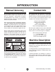
INTRODUCTION Manual Accuracy Contact Info We are proud to offer this manual with your new machine! We've made every effort to be exact with the instructions, specifications, drawings, and photographs of the machine we used when writing this manual. However, sometimes we still make an occasional mistake. We stand behind our machines. If you have any questions or need help, use the information below to contact us. Before contacting, please get the serial number and manufacture date of your machine.
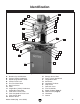
Identification B A C Y X D W E D V F U T S R G H Q H P I K I J O K L M N Figure 1. G0704 Identification. A. B. C. D. E. F. G. H. I. J. K. L. M. Drawbar Cap and Drawbar Vertical (Z-Axis) Handwheel Speed Range Selector Knob Vertical Travel Lock Fine Feed Lock Knob Quill Feed Lever Table Longitudinal (X-Axis) Handwheel Longitudinal Table Stop Table Cross Travel Locks Table Longitudinal Travel Lock Table Center Stop Machine Stand Model G0704 (Mfg. since 09/09) N. Storage Access Door O.
Electronic Controls Identification A B K J H I C G F D E Figure 2. G0704 electronic controls identification. A. B. C. D. E. F. -4- Spindle RPM Readout Spindle Digital Readout OFF Button Digital Readout ON/ZERO Button Digital Readout Battery Cover & Battery Spindle Depth Display DECREASE Button Spindle Depth Display INCREASE Button G. IN/MM Unit Selection Button H. Spindle Depth Display I. Spindle Direction Selection Knob J. Variable Spindle Speed Knob K.
MACHINE DATA SHEET Customer Service #: (570) 546-9663 · To Order Call: (800) 523-4777 · Fax #: (800) 438-5901 MODEL G0704 DRILL/MILL WITH STAND Product Dimensions: Weight.............................................................................................................................................................. 265 lbs. Width (side-to-side) x Depth (front-to-back) x Height........................................................................... 38 x 24 x 31 in. Footprint (Length x Width).
Main Specifications: Operation Info Spindle Travel.............................................................................................................................................. 2 in. Longitudinal Table Travel.................................................................................................................... 18-7/8 in. Cross Table Travel................................................................................................................................ 6-7/8 in.
Features: Digital spindle scale reads metric, inches, zero, set, on/off Forward/reverse switch Chip guard Digital display for spindle speed Dovetail column Front mounted fine feed knob Coolant trough Accessories Included: Drill chuck 1/16-1/2 in.
SECTION 1: SAFETY For Your Own Safety, Read Instruction Manual Before Operating this Machine The purpose of safety symbols is to attract your attention to possible hazardous conditions. This manual uses a series of symbols and signal words intended to convey the level of importance of the safety messages. The progression of symbols is described below. Remember that safety messages by themselves do not eliminate danger and are not a substitute for proper accident prevention measures.
DISCONNECTING POWER SUPPLY.Alwaysdisconnect machine from power supply before servicing, adjusting, or changing cutting tools (bits, blades, cutters, etc.). Make sure switch is in OFF positionbeforereconnectingtoavoidanunexpectedorunintentionalstart. APPROVED OPERATION. Untrained operators can be seriously hurt by machinery. Only allow trained or properly supervised people to use machine.
Additional Safety for Mill/Drills UNDERSTANDING CONTROLS. Make sure you understand the use and operation of all controls. BE ATTENTIVE. DO NOT leave the mill/drill running unattended for any reason. Safety accessories. Always use a chip guard in addition to your safety glasses when milling/drilling to prevent bodily injury. DISCONNECT POWER.
SECTION 2: POWER SUPPLY Availability Circuit Requirements Before installing the machine, consider the availability and proximity of the required power supply circuit. If an existing circuit does not meet the requirements for this machine, a new circuit must be installed. To minimize the risk of electrocution, fire, or equipment damage, installation work and electrical wiring must be done by a qualified electrician in accordance with all applicable codes and standards.
Grounding & Plug Requirements This machine MUST be grounded. In the event of certain malfunctions or breakdowns, grounding reduces the risk of electric shock by providing a path of least resistance for electric current. This machine is equipped with a power cord that has an equipment-grounding wire and a grounding plug (similar to the figure below). The plug must only be inserted into a matching receptacle (outlet) that is properly installed and grounded in accordance with all local codes and ordinances.
SECTION 3: SETUP Needed for Setup This machine presents serious injury hazards to untrained users. Read through this entire manual to become familiar with the controls and operations before starting the machine! Wear safety glasses during the entire set up process! The Model G0704 is a heavy machine. Serious personal injury may occur if safe moving methods are not used. To be safe, get assistance and use power equipment to move the shipping crate and remove the machine from the crate.
Inventory The following is a description of the main components shipped with your machine. Lay the components out to inventory them. A If any non-proprietary parts are missing (e.g. a nut or a washer), we will gladly replace them; or for the sake of expediency, replacements can be obtained at your local hardware store. Contents Qty A. Mill/Drill w/Stand.......................................... 1 B. Open End Combo Wrench 17/19................. 1 C. Open End Combo Wrench 8/10.................. 1 D.
Cleanup The unpainted surfaces of your machine are coated with a heavy-duty rust preventative that prevents corrosion during shipment and storage. This rust preventative works extremely well, but it will take a little time to clean. Be patient and do a thorough job cleaning your machine. The time you spend doing this now will give you a better appreciation for the proper care of your machine's unpainted surfaces.
Site Considerations Weight Load Physical Environment Refer to the Machine Data Sheet for the weight of your machine. Make sure that the surface upon which the machine is placed will bear the weight of the machine, additional equipment that may be installed on the machine, and the heaviest workpiece that will be used. Additionally, consider the weight of the operator and any dynamic loading that may occur when operating the machine.
Moving & Placing Machine The Model G0704 is a heavy machine. Serious personal injury may occur if safe moving methods are not used. To be safe, get assistance and use power equipment to move the shipping crate and remove the machine from the crate. To remove your machine from the shipping crate and place it in position: 1. Place the crate adjacent to the location where your machine will be placed, then remove the shipping crate from the pallet. 5.
Mounting to Shop Floor Although not required, we recommend that you mount your new machine cabinet to the floor. Because this is an optional step and floor materials may vary, floor mounting hardware is not included. Generally, you can either bolt the cabinet to the floor or mount it on machine mounts. Both options are described below. Whichever option you choose, it is necessary to level the cabinet with a precision level.
Assembly Drill Chuck Arbor Assembly of the Model G0704 consists of attaching the four handwheel handles to the machine. Your machine includes an B-16 drill chuck arbor and drill chuck. Before use, the drill chuck must be installed onto the arbor. The This drill chuck installation is intended to be semi-permanent. To assemble your machine: 1. With a #3 standard screwdriver, install the large handwheel handle on the elevation handwheel (Figure 11).
Power Connection After you have completed all previous setup instructions and circuit requirements, the machine is ready to be connected to the power supply. Disconnecting Power 1. Turn the machine power switch OFF. 2. Grasp the molded plug and pull it completely out of the receptacle. Do not pull by the cord as this may damage the wires inside. To avoid unexpected startups or property damage, use the following steps whenever connecting or disconnecting the machine. Connecting Power 1.
Test Run & Spindle Break-in The Model G0704 spindle speed can be set from 50–2250 RPM. You must follow the proper breakin procedures to ensure the spindle bearings break-in and seat before putting any milling load on the machine. To test run and break-in the spindle bearings: 1. —When operating correctly, the machine runs smoothly with little or no vibration or rubbing noises. — Investigate and correct strange or unusual noises or vibrations before operating the machine further.
SECTION 4: OPERATIONS Basic Controls To reduce the risk of serious injury when using this machine, read and understand this entire manual before beginning any operations. Damage to your eyes and lungs could result from using this machine without proper protective gear. Always wear safety glasses and a respirator when operating this machine. Use the descriptions and figures below to become familiar with the basic controls of your machine. Vertical Handwheel: Raises and lowers the headstock (Z-Axis).
Drawbar Cap: Covers the drawbar and upper portion of the spindle. Spindle RPM Readout: Displays the speed of the spindle rotation. Drawbar: Secures collets and tooling in the spindle taper. Emergency STOP Button: Interrupts the flow of power to the machine. Spindle and Chuck: Provide a mounting place for tooling. Variable Spindle Speed Knob: Changes the speed of the spindle rotation. Quill Lock Lever: Locks the vertical position of the quill when tightened.
SECTION 4: OPERATIONS Operation Overview The purpose of this overview is to provide the novice machine operator with a basic understanding of how the machine is used during operation, so the machine controls/components discussed later in this manual are easier to understand. Due to the generic nature of this overview, it is not intended to be an instructional guide.
Digital Readout Unit The digital readout unit gives a precise reading of the vertical positioning of the quill. It can be zeroed at any position and manually increased or decreased independent of quill position when the operation requires it (Figure 22). OFF Button ON/0 Button IN/MM Button To use the digital readout: 1. 2. Press the IN/MM button to select whether units will be displayed in inches or millimeters. Each press of the button switches from one unit to the other. 3.
Calculating Spindle Speed Closely follow the proper spindle speed and proper feed rate to produce good results, reduce undue strain on all moving parts and increase operator safety. Prior to milling, determine the spindle speed needed to cut your workpiece, then set the speed on the machine. To determine the needed spindle speed: 1. Use the table in Figure 23 to determine the cutting speed required for the material of your workpiece. 2. Measure the diameter of your cutting tool in inches. 3.
Spindle Speed and Direction Note: It may be necessary to rotate the spindle by hand to get the gears to mesh properly. 3. Setting the speed on the Model G0704 is a two part process. The gearbox in the headstock has two gear ranges and the motor is a variable speed unit. Together, these two systems provide an overall speed range of 50–2250 RPM. To set the spindle speed: 1. Make sure the work area is clear and that all safety precautions are taken. 4.
Spindle Height Controls The spindle height is controlled by the quill feed lever and the fine feed knob. Fine Feed Knob Changing Spindle Position Using Fine Feed Knob 1. Unlock the quill lock lever and tighten the fine feed lock knob. 2. Rotate the fine feed knob to lower or raise the spindle in small increments. Observe the scale on the knob or the digital readout to monitor movement in thousandths of an inch (Figure 27).
Drill Chuck To install the drill chuck and arbor: 1. DISCONNECT MILL/DRILL FROM POWER! 2. Remove the drawbar cap. 3. Insert the chuck arbor into the spindle, making sure to line up the slot in the arbor with the pin in the spindle. 4. Thread the drawbar into the arbor until the arbor is seated up into the spindle taper. 5. Use a 17mm wrench to prevent the spindle from turning while you use an 8mm wrench to snug the drawbar, as shown in Figure 28. Figure 28. Snugging the drawbar.
Loading Tooling Your Model G0704 features an R-8 spindle taper, which gives the freedom to use standard R-8 cutting tools and collets. These optional collets come in many sizes, typically ranging from 1⁄ 16" to 7 ⁄ 8" and 3mm to 20mm, and should be matched to your cutting tool shank size. To install the tooling: 1. DISCONNECT MILL/DRILL FROM POWER! To remove the collet: 1. DISCONNECT MILL/DRILL FROM POWER! 2. Remove the drawbar cap. 3. Lock the quill in place with the quill lock lever. 4.
Headstock Travel (Z-Axis and Rotation) Headstock height is adjustable in the vertical Z-axis to accept large workpieces. For unique milling operations, the headstock can be tilted right or left between 0° and 90°. To raise or lower the headstock: 1. Unlock the vertical travel lock levers shown in Figure 29. Vertical Handwheel To tilt the headstock to the left or right: 1.
Table Travel X-Axis Handwheels The mill/drill table can be moved in the longitudinal (X-axis) and cross (Y-axis) directions. Longitudinal Feed The X-axis is moved by the handwheels shown in Figure 31 at the end of the table. These handwheels will move the table in both directions side-to-side. One complete revolution of either handwheel moves the longitudinal feed 0.100". There is also a scale on the front of the table for use when a tight tolerance is not required.
ACCESSORIES SECTION 5: ACCESSORIES Some aftermarket accessories can be installed on this machine that could cause it to function improperly, increasing the risk of serious personal injury. To minimize this risk, only install accessories recommended for this machine by Grizzly. H8177—Worktable with Angle Enjoy having an economical way to support your workpiece at an array of angles. This high-quality tilting worktable is quick and easy to setup and use. NOTICE Refer to www.grizzly.
G9322—Boring Head Combo Set Hardened and ground adjusting screws along with a wide base design guarantee a long life and trouble-free use. Includes a 2" boring head, R-8 arbor with 7/16"-20 TPI, and a 12 piece 3/4" boring bar set. T10067—8 Pc. R-8 Quick Change Collet Set T10068—16 Pc. R-8 Quick Change Collet Set These are the best collet sets we've ever carried. They can be used in production shops and for high precision work.
G9511—T-Slot Nuts, 4 PK, 7/16" Slot, 3/8"-16 Heat treated steel T-Slot Nuts with black oxide finish feature an imperfect thread in the base of the T-nut to eliminate any danger of screwing the clamping stud through and damaging the table slot. G9849—Magnetic Base/Dial Indicator Combo Precision measurements and setups have never been so easy. Magnetic base engages with just the turn of a switch and allows pinpoint adjustment. The dial indicator features 0-1" travel and has a resolution of 0.001".
SECTION 6: MAINTENANCE Always disconnect power to the machine before performing maintenance. Failure to do this may result in serious personal injury. Schedule For optimum performance from your machine, follow this maintenance schedule and refer to any specific instructions given in this section. Figure 44. Vertical way lube location (both sides). Daily Check: • Make sure mill/drill is disconnected from power when not in use. • Check for loose mounting bolts.
Every six months, or more frequently under heavy use, we recommend that you clean and lubricate the leadscrews and vertical handwheel gears with a light machine oil and multi-purpose grease. 6. Tools Needed: Qty Hex Wrench 3, 4mm........................................... 1 Multi-Purpose Lithium Grease............................ 1 Paint Brush for Grease Application.................... 1 Oil Bottle of 10-30w Synthetic Oil...................... 1 Stiff-Bristled Nylon Brush for Cleaning...............
To lubricate the vertical leadscrew bushing and ring & pinion gears: 1. 5. Remove the acorn nut and flat washer that secure the vertical handwheel, then remove the handwheel (Figure 52). DISCONNECT MILL/DRILL FROM POWER! 2. Remove the bushing cap by unthreading the four cap screws that secure it (Figure 50). Bushing Cap Figure 52. Handwheel removal. 6. Figure 50. Bushing cap removal.
Troubleshooting SECTION 7: SERVICE Review the troubleshooting and procedures in this section if a problem develops with your machine. If you need replacement parts or additional help with a procedure, call our Technical Support at (570) 546-9663. Note: Please gather the serial number and manufacture date of your machine before calling. Troubleshooting Symptom Possible Cause Possible Solution Machine does not start. 1. Circuit breaker on machine tripped. 1.
Symptom Possible Cause Tool slips in collet. 1. Collet is not fully drawn up into 1. Tighten drawbar. spindle taper. 2. Measure tool shank diameter and match with 2. Wrong size collet. appropriate diameter collet. 3. Debris on collet or in spindle taper. 3. Clean collet and spindle taper. 4. Lessen depth of cut and allow chips to clear. 4. Taking too big of a cut. Breaking tools or cutters. 1. Spindle speed too slow/feed rate is 1. Set spindle speed correctly (Page 27) or use a slower feed rate.
Gibs Gibs are wedge-shaped pieces of metal that fill the gap between the sliding surfaces of the machine. By adjusting the position of the gib in its gap, you can remove any play that might exist between the adjacent components. The gibs are pre-adjusted at the factory but due to storage, break-in, and usage, may require adjustment. If movement seems too tight at first, make sure that all the rust preventative that was shipped on the machine is removed from the ways.
Leadscrew Backlash When you turn the handwheels to adjust the position of the table, you will notice slight play (backlash) in the handwheel before the table begins to move. If this play is greater than 0.008" (measured with the dial at the base of each handwheel), then you will need to adjust the leadscrew nuts. To reach the adjustment screws on the leadscrew nut, you may have to fabricate extensions for your hex wrenches. When adjusting, make adjustments in small increments.
Motor Service 3. Unscrew one of the brush caps to expose the brush assembly (Figure 59). The bearings inside the motor are shielded and lubricated for the life of the bearing and require no routine maintenance. This motor is equipped with long life carbon brushes. Brush life expectancy is affected by motor loading. Heavy motor loading will result in reduced brush life. If you notice a loss in power or if the motor becomes excessively noisy, inspect the brushes.
machine SECTION 8: WIRING These pages are current at the time of printing. However, in the spirit of improvement, we may make changes to the electrical systems of future machines. Compare the manufacture date of your machine to the one stated in this manual, and study this section carefully. If there are differences between your machine and what is shown in this section, call Technical Support at (570) 546-9663 for assistance BEFORE making any changes to the wiring on your machine.
Wiring Diagram 1 3 Neutral 3 P3 1 P1 2 2 1 A1 P2 Hot 5 2 Circuit Board See Figure 61 L1 L2 7 110 VAC 24 5-15 Plug Ground 14 Guard Limit Switch See Figure 62 A Fuse Holder PE N L 10A L Spindle RPM Sensor LO LO L1 L1 IN N PE 11 N E L 1 B A Circuit Board See Figure 64 OUT N E 13 L PE PE V 23 Motor Brushes GND 24 PE Motor 110V 1HP 93ZYT-005 750W 60Hz GND RPM Display 24 10 A1 24 23 23 13 13 24 14 10 2 11 24 24 10 12 11 9 6 8 7 5 2 4 3 1 On
Electrical Components -46- Figure 61. Rear panel. Figure 63. Control panel wiring. Figure 62. Chip guard limit switch. Figure 64. Side panel. READ ELECTRICAL SAFETY ON PAGE 44! Model G0704 (Mfg.
SECTION 9: PARTS Column Breakdown 3 1 2 31 31-1 32 13 16 25 4 5 14 15 6 17 7 3 33 34 35 10 19 27 40 47 46 41 45 36 42 42 43 29 11 12 39 38 8 18 37 26 28 9 36 42 20 48 21 24 49 30 22 23 19 19 52 51 50 19 58 59 7 60 64 66 67 68 15 14 54 44 57 55 77 56 65 61 69 73 63 62 72 16 70 76 60 16 71 44 75 74 59 60 57 40 58 51 39 Model G0704 (Mfg.
Column Parts List REF PART # DESCRIPTION REF PART # DESCRIPTION 1 2 3 4 5 6 7 8 9 10 11 12 13 14 15 16 17 18 19 20 21 22 23 24 25 26 27 28 29 30 31 31-1 32 33 34 35 36 37 38 VERTICAL SLIDE SET SCREW M6-1 X 16 FLAT WASHER 8MM LOCK WASHER 8MM CAP SCREW M8-1.25 X 25 FLAT WASHER 12MM LOCK WASHER 12MM CAP SCREW M12-1.75 X 40 T-BOLT M10-1.5 FLAT WASHER 10MM LOCK WASHER 10MM HEX NUT M10-1.5 BLOCK BRASS PIN LOCK LEVER GIB SCREW VERTICAL GIB ANGLE SCALE CAP SCREW M5-.8 X 10 DUST COVER HEX NUT M5-.
Electrical Box Breakdown & Parts List 93 94 90 94 78 92 91 80 86 87 91 81 86 80-1 83 88 89 85 84 79 95 REF PART # DESCRIPTION REF PART # DESCRIPTION 78 79 80 80-1 81 83 84 85 86 SPEED CONTROL CIRCUIT BOARD VARIABLE SPEED KNOB CAP SCREW M3-.5 X 16 HEX NUT M3-.5 MAIN CIRCUIT BOARD ON/OFF SWITCH CAP SCREW M4-.7 X 10 CONTROL PANEL CAP SCREW M4-.7 X 6 87 88 89 90 91 92 93 94 95 SPINDLE RPM READOUT ELECTRICAL BOX CAP SCREW M5-.
Headstock Breakdown 206-2 206-1 208 209 221-2 209-2 201 221-1 209-1 202 219 220 210 203 221 211 204 231 222 223 212 225-2 205 225 229 224 225-1 228 227 215 213 230 214 206 226 239 211 207 240 216 217 218 210 234-1 234-2 238 275 274 240 234 266 273 236 237 235 233 242 265 252 241 232 276 243 245 244 254 251 248 250 -50- 264 263 262 276 261 260 259 258 257 247 256 246-2 243 249 248 272 271 270 269 268 267 246-1 246 255 255-1 Model G0704 (Mfg.
Headstock Parts List REF PART # DESCRIPTION REF PART # DESCRIPTION 201 202 203 204 205 206 206-1 206-2 207 208 209 209-1 209-2 210 211 212 213 214 215 216 217 218 219 220 221 221-1 221-2 222 223 224 225 225-1 225-2 226 227 228 229 230 231 232 233 234 234-1 234-2 QUILL RETANING CLIP BUSHING COMPRESSION SPRING EXT RETAINING RING 45MM BALL BEARING 6209ZZ GEARS 60/70T SPINDLE RING 16MM CAP SCREW M3-.5 X 8 BALL BEARING 7007-OPEN EXT RETAINING RING 15MM GEAR 37T GUARD CAP SCREW M3-.
Chip Guard Breakdown & Parts List 281 277 278 280 279 282 283 276 284 285 286 287 289 288 REF PART # DESCRIPTION REF PART # DESCRIPTION 276 277 278 279 280 281 282 CAP SCREW M3-.5 X 16 FLAT WASHER 3MM HEX NUT M3-.5 CAP SCREW M4-.7 X 20 EXT RETAINING RING 12MM WAVY WASHER 20MM GUARD MOUNTING BLOCK 283 284 285 286 287 288 289 COPPER SPACER GUARD LIMIT SWITCH PROTECTIVE PAPER SET SCREW M5-.8 X 10 CHIP GUARD POST CHIP GUARD CAP SCREW M4-.
Labels Breakdown & Parts List 301 303 302 309 304 308 305 306 307 REF PART # DESCRIPTION REF PART # DESCRIPTION 301 302 303 304 305 READ MANUAL LABEL SAFETY GLASSES LABEL MACHINE ID LABEL HIGH/LOW SPEED LABEL PUTTY TOUCH-UP PAINT 306 307 308 309 MODEL NUMBER LABEL GREEN TOUCH-UP PAINT CUTTER WARNING LABEL ENTANGLEMENT LABEL PLABEL-12C PLABEL-11B P0704303 P0704304 PPAINT-11 P0704306 PPAINT-1 P0704308 PLABEL-55C Safety labels warn about machine hazards and ways to prevent injury.
NOTES -54- Model G0704 (Mfg.
WARRANTY CARD Name _____________________________________________________________________________ Street _____________________________________________________________________________ City _______________________ State _________________________ Zip _____________________ Phone # ____________________ Email ________________________ Invoice # _________________ Model # ____________________ Order # _______________________ Serial # __________________ The following information is given on a voluntary basis.
FOLD ALONG DOTTED LINE Place Stamp Here GRIZZLY INDUSTRIAL, INC. P.O.
WARRANTY AND RETURNS WARRANTY AND RETURNS Grizzly Industrial, Inc. warrants every product it sells for a period of 1 year to the original purchaser from the date of purchase. This warranty does not apply to defects due directly or indirectly to misuse, abuse, negligence, accidents, repairs or alterations or lack of maintenance.
Buy Direct and Save with Grizzly ® – Trusted, Proven and a Great Value! ~Since 1983~ Visit Our Website Today For Current Specials! ORDER 24 HOURS A DAY! 1-800-523-4777