MODEL G0648 WELDING FUME EXTRACTOR OWNER'S Manual Copyright © SEPTEMBER, 2008 By Grizzly Industrial, Inc. Warning: No portion of this manual may be reproduced in any shape Or form without the written approval of Grizzly Industrial, inc.
4HIS MANUAL PROVIDES CRITICAL SAFETY INSTRUCTIONS ON THE PROPER SETUP OPERATION MAINTENANCE AND SERVICE OF THIS MACHINE EQUIPMENT &AILURE TO READ UNDERSTAND AND FOLLOW THE INSTRUCTIONS GIVEN IN THIS MANUAL MAY RESULT IN SERIOUS PERSONAL INJURY INCLUDING AMPUTATION ELECTROCUTION OR DEATH 4HE OWNER OF THIS MACHINE EQUIPMENT IS SOLELY RESPONSIBLE FOR ITS SAFE USE 4HIS RESPONSIBILITY INCLUDES BUT IS NOT LIMITED TO PROPER INSTALLATION IN A SAFE ENVIRONMENT PERSONNEL TRAINING AND USAGE AUTHORIZATION PROPER INS
Table of Contents INTRODUCTION................................................ 2 Foreword......................................................... 2 Contact Info.................................................... 2 Functional Overview....................................... 2 Identification.................................................... 3 SECTION 1: SAFETY........................................ 6 Safety Instructions for Machinery................... 6 Additional Safety Instructions for ................
INTRODUCTION Foreword Functional Overview We are proud to offer the Model G0648 Welding Fume Extractor. This machine is part of a growing Grizzly family of fine metalworking machinery. When used according to the guidelines set forth in this manual, you can expect years of trouble-free, enjoyable operation and proof of Grizzly’s commitment to customer satisfaction.
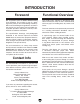
Identification K A B L J C D I M E H N G P F O Figure 1. Features. A. Main Blast Gate: Provides control for intermittent suction for the suction hood. I. Rolling-Filter Supply Cabinet: Location for the fresh roll of filter paper. B. Ducting Support System: Frame and lock levers provide for suction hood positioning. J. Rotation Joint: Provides continuous 360° rotation of the ducting assembly. C. Downdraft Table Port & Blast Gate: For optional welding downdraft table connection. K.
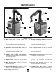
MACHINE DATA SHEET Customer Service #: (570) 546-9663 • to order Call: (800) 523-4777 • Fax #: (800) 438-5901 MODEL G0648 WELDING FUME EXTRACTOR product Dimensions: Weight ............................................................................................................................................................................ 728 lbs length/Width/height ..............................................................................................................................
Filter Vibrating Motor power ........................................................................................................................................................................ 25W Voltage ..................................................................................................................................................................... 220V amps ..............................................................................................................................
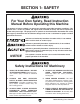
3%#4)/.
3AFETY )NSTRUCTIONS FOR -ACHINERY /.,9 !,,/7 42!).%$ !.$ 02/0 %2,9 350%26)3%$ 0%23/..%, 4/ /0%2!4% -!#().%29 BV`Z hjgZ deZgVi^dc ^chigjXi^dch VgZ hV[Z VcY XaZVgan jcYZghiddY# +%%0 #(),$2%. !.$ 6)3)4/23 !7!9 @ZZe Vaa X]^aYgZc VcY k^h^idgh V hV[Z Y^h" iVcXZ [gdb i]Z ldg` VgZV# -!+% 7/2+3(/0 #(),$02//& JhZ eVYadX`h! bVhiZg hl^iX]Zh! VcY gZbdkZ hiVgi hl^iX] `Znh# .%6%2 ,%!6% 7(%. -!#().% )3 25..).
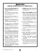
Additional Safety Instructions for Welding Fume Extractors 1. WELDING FUMES. Welding fumes are hazardous and can cause lung damage without warning. Keep your head out of welding fumes. Use adequate ventilation at the arc to safely remove the fumes from your breathing zone and the general area. Use ANSI approved respirators for the type of welding operation. Protect others from these fumes. 2. PROTECT BODY FROM ARC BURNS, SPARKS, AND SPATTER. Wear correct and approved eye and body protection.
Meeting Welding Fume Extraction Codes and Standards Welding, cutting, brazing, or soldering of metals can give off poisonous fumes containing zinc, lead, beryllium, cadmium, mercury, fluorine, and hexavalent chromium and others. These fumes typically originate from fluxes, solders, anti-corrosion coatings, pigments, metal fillers, and residual chemicals on the workpiece. This machine is designed to help meet the new welding shop clean air requirements mandated by OSHA.
SECTION 2: CIRCUIT REQUIREMENTS 220V 3-Phase Operation Power Connection The power connection device depends on the type of installed or planned service. We recommend using a NEMA15-15 plug and receptacle shown in Figure 2.
SECTION 3: SETUP Setup Safety This machine presents serious injury hazards to untrained users. Read through this entire manual to become familiar with the controls and operations before starting the machine! Items Needed for Setup The following items are needed to complete the setup process, but are not included with your machine: Description Qty • Hex Wrench 3/16" . ....................................... 1 • Wrench 12mm............................................. 1 • Assistant or Hoist..................
Inventory The following is a description of the main components shipped with your machine. Lay the components out to inventory them. B C A Note: If you can't find an item on this list, check the mounting location on the machine or examine the packaging materials carefully. Occasionally we pre-install certain components for shipping purposes. Crate 1: (Figure 3) Qty A.. Welding Fume Extractor Unit...................... 1 B.. Button Head Cap Screws 3/8"-16 x 1" . (Ducting Arm)...............................
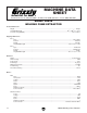
Hardware Recognition Chart G0648 Welding Fume Extractor -13-
L6AA DUCTING WORK ZONE RADIUS Floor Load Refer to the Machine Data Sheet for the weight and footprint specifications of your machine. Some floors may require additional reinforcement to support both the machine and operator. 24" MINIMUM OUTPUT CLEARANCE OVERHEAD SUCTION CONNECTION ONLY RECYCLED AIR BASIC WELDING BENCH Placement Location This machine is designed to operate when the ambient temperature is between 41°F and 122°F, and when the humidity is between 30% and 95%.
Ducting Arm Installation To install the ducting arm: 1. Remove the six button head cap screws and flat washers that surround the 6" intake port on top of the machine. Test Run Once the ducting has been attached, test run your machine to make sure it runs properly. If, during the test run, if you cannot easily locate the source of an unusual noise or vibration, stop using the machine immediately, then review the Troubleshooting on Page 34. 2.
4. Completely open both blast gates on the ducting arm (Figure 8). 8. Push the ON/OFF button. The OPERATING LAMP will go out and the FILTER CLEANING lamp will light. The lamp indicates that as soon as the fan completely stops, the vibrating filter is set to operate in three short durations for approximately 3 seconds each. 9. When the vibrating filter is finished, push the ON/OFF button and restart the machine. 10. On the control panel, push the ON/OFF button. Figure 8. Ducting blast gates. 5.
SECTION 4: OPERATIONS Operation Safety To reduce the risk of serious injury when using this machine, read and understand this entire manual before beginning any operations. Damage to your eyes and lungs could result from using this machine without proper protective gear. Always wear the appropriate respirator and welding helmet fitted with the correct type of eye protection when welding and operating this machine.
5. Press the ON/OFF button. The OPERATING LED will light, and the machine will start momentarily. 6. Observe the digital display and make sure the EXHAUSTING TIME and FILTER ROLLING TIME values are at your last setting, or at least at the factory initial settings for EXHAUSTING TIME, and for FILTER ROLLING TIME. 7. 8.
Control Panel Operation A. EXHAUSTING TIME (min): Displays, in minutes, how much welding time is allotted before new filter paper is exposed. N. FILTER INDICATOR Lamp: Lights when the vibrating filter needs to be cleaned or replaced. B. FILTER ROLLING TIME (sec): Displays, in seconds, the duration of roller-filter advance. O. FILTER INDICATOR Lamp: Lights when the HEPA filter needs to be cleaned or replaced. C. FILTER CLEANING: Lamp lights when the vibrating-type filter is being de-caked. D.
Changing RollingFilter Timing As the rolling-type filter becomes clogged, the EXHAUSTING TIME and ROLLING TIME should be set to advance the rolling type filter as to expose just enough filter paper so that a good working CFM is maintained. This is accomplished by unrolling just enough filter paper to maintain adequate suction at the point of welding. The general idea is to initially find the point at which the filter paper begins to clog and suction begins to drop off.
G0648 Welding Fume Extractor 10 15 20 25 30 40 x x x x x x x x x x x x x x x x x x 250 167 125 100 83 63 Cycles 250 167 125 100 83 63 Cycles 250 167 125 100 83 63 Cycles 9-7/16" 14-3/16" 18-7/8" 23-5/8" 28-3/8" 37-3/4" = = = = = 15 20 25 30 40 Length Rolled (Approx.
SECTION 5: ACCESSORIES T20474—First Layer Stainless Screen Made of high-quality stainless steel, this 1mm removable mesh arrests sparks and stops hot slag from entering the machine. T20529—Third Layer Filter This vibrating filter, collects 85% of the 1-micron particles. Figure 11. Replacement screen for G0648. T20475—Second Layer Paper Filter Roll This rolling-type paper filter is the consumable workhorse filter of your machine. It removes most all of the 10-micron and larger grit, dust, and oily smoke.
H5297 6" Welding Fume Collection Kit Our starter kit includes everything you will need for a simple, single machine set up at one low price. The branch and end cap makes your fume extraction system expansion ready for future growth. The an addition kit will allow you to expand as your shop gets bigger.
H7786—Auto Darkening Welding Helmet Automatic UV and IR filters protect eyes from harmful visible and invisible light during welding. Switching time is less than or equal to 2 milliseconds, so there's no need to flip the helmet up to see your work under normal light conditions. Full face protection features adjustable head suspension and adjustable delay time, sensitivity and dark shade protection. Viewing area is 31⁄ 2" x 11⁄ 2". Includes 2 AAA batteries. Figure 19. Model H7786 welding helmet.
SECTION 6: MAINTENANCE Lubrication Always disconnect power to the machine before performing maintenance. Failure to do this may result in serious personal injury. Use a dry rag to wipe all drive chains and sprockets clean; then brush the chain links with a thin coat of light machine oil. Refer to Figure 23 for locations. Schedule Electric Eye For optimum performance from your machine, follow this maintenance schedule and refer to any specific instructions given in this section.
Slag-Screen Cleaning Make sure that you clean the slag screen often and inspect for holes or damage. Under correct use, this screen should last for years. Tools Needed Qty Soft Brass Wire Brush........................................ 1 OSHA Approved Respirator............................... 1 Shop Vacuum..................................................... 1 To perform this procedure: 1. UNPLUG THE MACHINE! 2. Put on your respirator, unlock and remove the slag drawer, and then the screen (Figure 24).
Rolling-Filter Replacement 3. While holding the axle, push on the springloaded spindle and swing the axle out and away from the spindle cone (Figure 27). Axle Spindle Cone This rolling-type paper filter is the consumable workhorse filter of your machine. It removes most of the 10-micron and larger grit, dust, and oily smoke. Tools Needed Qty OSHA Approved Respirator............................... 1 To perform this procedure: 1.
8. Unwind approximately 15" of filter paper and fold approximately 6" over one of the conveyor ribs so when you push the manual feed button (Figure 29), the conveyor will draw the paper through the machine and into the recovery cabinet. Note: For assistance, you can use a couple of pieces of tape to hold the filter paper on the conveyor. 12. Remove the end of the filter paper from the conveyor, and then carefully pull the filter paper so approximately 15" of paper extends from the machine. 13.
Vibrating Filter (Manual Cleaning) The vibrating filter collects 85% of the 1-micron particles. This filter rarely needs to be replaced if the machine is used properly and the filter is periodically removed and manually cleaned. Tools Needed Qty Wrench 17mm.................................................... 1 Wrench 14mm.................................................... 1 OSHA Approved Respirator............................... 1 Safety Goggles...................................................
8. Unplug the vibration motor, lift the vibrating filter upward and pull the bottom outward (Figure 36). Place the unit on the floor. 10. Using warm soapy water, wash out the filter cabinet and dust drawer, and allow them to air-dry. 11. Inspect for any seal or gasket damage and replace as required. Vibration Motor 12. Make sure you are wearing your respirator and safety goggles. 13.
18. Grasp the spring and insert the top of it on the end of the retaining bolt that protrudes into the cabinet. Note: With the top of the spring being held in place by the end of this bolt, compressing and positioning the bottom of the spring into its seat is much easier. 19. When the spring is installed, thread the retaining bolt by hand all the way down until it seats into the hole in the top of the vibrating filter and stops. 20.
HEPA Filter (Manual Cleaning) This HEPA filter removes 99.97% of the 0.3-micron particles. This filter rarely needs to be replaced if the machine is properly used and cleaned. Tools Needed Qty OSHA Approved Respirator............................... 1 Safety Goggles................................................... 1 Air Compressor.................................................. 1 Blowgun.............................................................. 1 3.
4. Using warm soapy water, wash out the filter housing and allow it to air dry. 8. After cleaning, return the filter to the marked position in the filter housing. 5. Make sure you are wearing your respirator and safety goggles. 9. Reassemble and start the machine. 6. Support the HEPA filter element and vacuum the input side of the filter with a soft brushtype tip while tapping the filter element. 7.
SECTION 7: SERVICE Review the troubleshooting and procedures in this section to fix or adjust your machine if a problem develops. If you need replacement parts or you are unsure of your repair skills, then feel free to call our Technical Support at (570) 546-9663. Troubleshooting Motor and Electrical Symptom Machine start. will Possible Cause 5. Relay at fault. 1. Reset or replace emergency stop switch. 2. Have electrician correct power supply problem. 3. Have repair for wiring problems. 4.
Operation Symptom Possible Cause Possible Solution Suction CFM is lower than normal. 1. Blast gate is leaking or is not completely open. 1. Make sure appropriate blast gate(s) are completely open and do not leak. 2. Door or cabinet is at fault. 2. Make sure that all doors are closed seals do not leak. 3. Reduce length of ducting; maintain 6" diameter ducting; eliminate as many bends as possible; move downdraft table closer to fume extractor. 4. Remove slag drawer and clean slag screen. 5.
SECTION 8: WIRING These pages are current at the time of printing. However, in the spirit of improvement, we may make changes to the electrical systems of future machines. Study this diagram carefully. If you notice differences between your machine and these wiring diagrams, call Technical Support at (570) 546-9663 for assistance. Electrical Safety Instructions 1. SHOCK HAZARD. Disconnect the power from the machine before servicing electrical components.
Wiring Overview 1 7 2 3 5 4 6 3 1 8DCIGDA E6C:A 8 (Page 40) GDAA>C< ;>AI:G GDAA>C< BDIDG ;>AI:G BDIDG EJH=7JIIDC HL>I8= D (Page 42) 2 (Page 42) 8DCK:NDG BDIDG 8DCK:NDG BDIDG EJH=7JIIDC HL>I8= A 4 EG:HHJG: H:CHDGH GDAA>C< ;>AI:G H:CHDG :N: 6 (Page 42) 7 F (Page 42) E 5 B6>C :A:8IG>86A 7DM B ;6C BDIDG (Page 38) ;>AI:G K>7G6I>DC BDIDG (Page 42) 8 C 220 VAC 3-PH (Page 38) G0648 Welding Fume Extractor READ ELECTRICAL SAFETY ON PAGE 36! -37-
Main Electrical Box Wiring MAIN ELE BOX NEMA 15-15 PLUG (as recommended) 3-PHASE 220 VAC
Main Electrical Box Components Figure 43. Input relay, fuse bus, phase controller. Figure 47. Transformer. Figure 48. Contactor and thermal relay. Figure 44. Pigtail. Figure 49. Split phase capacitors. Figure 45. Main terminal block. Figure 46. Rheostat. G0648 Welding Fume Extractor Figure 50. Main electrical box.
Control Panel Wiring MAIN ELE CNTRL View this page in color at www.grizzly.com.
Control Panel Electrical Components Figure 54. Control panel terminal block. Figure 51. NOR/SET control. Figure 55. Emergency stop switch. Figure 56. Vibrating filter lamp. Figure 58. HEPA filter lamp. Figure 52. Digital control panel circuit board. Figure 53. Filter warning buzzer. Figure 57. Control box.
Cabinet Wiring MAIN ELE MOT 8DCK:NDG ;>AI:G BDIDG (Figure 67) View this page in color at www.grizzly.com. , H:CHDG (Figure 65) - 8DCK:NDG BDIDG EJH= 7JIIDC (Figure 68) 6 &% ID B6>C I:GB>C6A 7AD8@ (Page 38) J& ) K>7G6I>DC BDIDG L& K& (Figure 63) * .
Cabinet Electrical Components Figure 66. Rolling filter motor circuit board. Figure 63. Vibrating filter motor. Figure 67. Rolling filter motor. Figure 59. Vibrating filter. Figure 64. Conveyor switch. Figure 65. Electric eye. Figure 68. Rolling filter switch. Figure 60. Conveyor motor. Figure 61. Pressure sensors. Figure 62. Fan motor. G0648 Welding Fume Extractor Figure 69. Cabinet components.
-44- *( ). )- *& ), *% +- +% +& +' ,* && +( &* &+ ,, &%*"& &%*"' ( )( ' &%) &%( -) -( ,- -% )& )% )' &' &) ,. &( &, +) +* ++ +, **. &% (, (- ''. ', )) (. (% +. ,( ,) ,+ ,' ,% (+ *+ )* )+ *) ** *, ,& *' (* () (( (' (& '' '( ') '* '+ '& '% &. &- -& * .. &%% -* &*, &%, &%+ &%& &%* &%' -) -( -- 48 -, G06 -+ -' . - , ) &*% .+ -. &*- &*. &)- &*& & + &(* &(+ &(- &)% &(. &)' &() &(( &(' &(& &(% &'( &'' &'&'& &'% &'.
Parts List REF PART # DESCRIPTION REF PART # DESCRIPTION 1 2 3 4 5 6 7 8 9 10 11 12 13 14 15 16 17 18 19 20 21 22 23 24 25 26 27 28 29 30 31 32 33 34 35 36 37 38 39 40 41 42 43 44 45 46 47 48 49 50 STAINLESS SCREEN ALUMINUM MESH 555 X 555 X 22MM DRAWER SPRING BUCKLE LATCH TAP SCREW #10 X 1 1/2 CABINET PLASTIC CAP SPECIAL RETAINING BOLT 3/8"-16 HEX NUT 3/8-16 OVAL SEAL PLEATED FILTER 600 X 170 X 730MM COMPRESSION SPRING VIBRATION MOTOR 220V HEX BOLT 1/4-20 X 1-1/2 HEX BOLT 5/16-18 X 3/4 VIBRATION MOTOR
Parts List REF PART # DESCRIPTION REF PART # DESCRIPTION 100 101 102 103 104 105 105-1 105-2 106 107 108 109 110 111 112 113 114 115 116 117 118 119 120 121 122 123 124 125 126 127 MOTOR BASE HEX BOLT 5/16-18 X 3/4 FLAT WASHER 5/16 FLAT WASHER 3/8 HEX NUT 3/8-16 MOTOR 2HP 220V 3PH FAN COVER MOTOR FAN HEX NUT 3/8-16 FLAT WASHER 3/8 HEX NUT 3/8-16 LOWER FRONT DOOR HANDLE ROTATION PLATE WATERPROOF SWITCH SWITCH HANDLE UPPER FRONT DOOR SPECIAL HEX BOLT M5-.
Blast Gates and Ducting Arm Breakdown '-. '.% '.& '.' '.- '%) '%% '-- ',' ',) ',* ',( '-, '-' '.) '.( '., ',+ '-+ '-* '%( ',% '+. ',, '.. '%' '%& ',& '.* '-) '.+ '+- ','-& '-( ',. '-% '** '+, '++ '+* '+) '+( '+% '+& '*'*.
Main Electrical Box (%% (%& (%' (%( (%) (%* (%+ (%, (%.
Label Placement 409 408 405 403 404 406 410 411 407 400 401 402 Parts List REF PART # DESCRIPTION REF PART # DESCRIPTION 400 401 402 403 404 405 P0648400 P0648401 PLABEL-63 P0648403 P0648404 P0648405 MACHINE ID LABEL MODEL ID LABEL DISCONNECT POWER LABEL CHANGE PLEATED FILTER LABEL CHANGE HEPA FILTER LABEL CHANGE ROLLING FILTER LABEL 406 407 408 409 410 411 POISON WARNING LABEL ELECTRICITY LABEL MAGNETIC FILTER TIME CHART RESPIRATOR LABEL WELDING WARNING LABEL READ MANUAL LABEL P0648406 PLAB
Notes -50- G0648 Welding Fume Extractor
7!22!.
;DA9 6ADC< 9DII:9 A>C: EaVXZ HiVbe =ZgZ '2)::,9 ).$5342)!, ).# 0 / "/8 "%,,).
WARRANTY AND RETURNS 7!22!.49 !.$ 2%452.
"UY $IRECT AND 3AVE WITH 'RIZZLY® n 4RUSTED 0ROVEN AND A 'REAT 6ALUE 6ISIT /UR 7EBSITE 4ODAY !ND $ISCOVER 7HY 'RIZZLY® )S 4HE )NDUSTRY ,EADER s 3%#52% /2$%2).' s /2$%23 3()00%$ 7)4(). (/523 s % -!), 2%30/.3% 7)4(). /.