MODEL G0456 VARIABLE SPEED WOOD LATHE OWNER'S MANUAL COPYRIGHT © NOVEMBER, 2005 BY GRIZZLY INDUSTRIAL, INC. REVISED JANUARY, 2007. WARNING: NO PORTION OF THIS MANUAL MAY BE REPRODUCED IN ANY SHAPE OR FORM WITHOUT THE WRITTEN APPROVAL OF GRIZZLY INDUSTRIAL, INC.
Safety labels warn about machine hazards and ways to prevent injury. The owner of this machine MUST maintain the original location and readability of the labels on the machine. If any label is removed or becomes unreadable, REPLACE that label before using the machine again. Contact Grizzly at (800) 523-4777 or www.grizzly.com to order new labels.
Table of Contents INTRODUCTION ............................................................................................................................... 3 Foreword .................................................................................................................................... 3 Contact Info ................................................................................................................................ 3 Machine Data Sheet............................................
SECTION 7: SERVICE ................................................................................................................... 30 Troubleshooting........................................................................................................................ 30 Aligning Headstock Spindle to Tailstock .................................................................................. 32 Replacing or Tightening V-Belt ..............................................................................
INTRODUCTION Foreword Contact Info We are proud to offer the Model G0456 Variable Speed Lathe. This machine is part of a growing Grizzly family of fine woodworking machinery. When used according to the guidelines set forth in this manual, you can expect years of trouble-free, enjoyable operation and proof of Grizzly’s commitment to customer satisfaction. If you have any comments regarding this manual, please write to us at the address below: We are pleased to provide this manual with the Model G0456.
Machine Data Sheet ������������� ����� ������������������������������������������������������������������������������������������ ������������������������������������� ��������������������������������������������������������������������������������������������������������������� ����������� ������������������� ��������������������������������������������������������������������������������������� ���������� ������������ ��������������������������������������������������������������������������������������
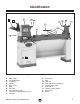
Identification A B C D E K L M N G J H F I P O Q R S Figure 1. Identification of main components. A. B. C. D. E. F. G. H. I. J. Miter Gauge 12" Sanding Disc Headstock Spindle Spur Center Bed Tool Rest Tool Rest Base Lock Tool Rest Height Adjustment Lock Tailstock G0456 Variable Speed Wood Lathe K. L. M. N. O. P. Q. R. S.
SECTION 1: SAFETY For Your Own Safety, Read Instruction Manual Before Operating this Machine The purpose of safety symbols is to attract your attention to possible hazardous conditions. This manual uses a series of symbols and signal words which are intended to convey the level of importance of the safety messages. The progression of symbols is described below. Remember that safety messages by themselves do not eliminate danger and are not a substitute for proper accident prevention measures.
Safety Instructions for Machinery 7. ONLY ALLOW TRAINED AND PROPERLY SUPERVISED PERSONNEL TO OPERATE MACHINERY. Make sure operation instructions are safe and clearly understood. 8. KEEP CHILDREN AND VISITORS AWAY. Keep all children and visitors a safe distance from the work area. 9. MAKE WORKSHOP CHILD PROOF. Use padlocks, master switches, and remove start switch keys. 10. NEVER LEAVE WHEN MACHINE IS RUNNING.
Additional Safety for Wood Lathes 1. KEEPING GUARDS IN PLACE. Make sure all guards are in place and that the lathe sits on a flat, stable surface. 2. EYE/FACE PROTECTION. Always wear eye protection or a face shield when operating the lathe. 3. RESPIRATORY PROTECTION. Always wear a respirator when using this machine. Wood dust may cause allergies or longterm respiratory health problems. 4. MOUNTING WORKPIECE.
SECTION 2: CIRCUIT REQUIREMENTS 220V Single-Phase Serious personal injury could occur if you connect the machine to the power source before you have completed the set up process. DO NOT connect the machine to the power source until instructed to do so. Grounding In the event of an electrical short, grounding reduces the risk of electric shock. The grounding wire in the power cord must be properly connected to the grounding prong on the plug; likewise, the outlet must be properly installed and grounded.
SECTION 3: SET UP Set Up Safety This machine presents serious injury hazards to untrained users. Read through this entire manual to become familiar with the controls and operations before starting the machine! Wear safety glasses during the entire set up process! The Model G0456 is a heavy machine. DO NOT over-exert yourself while unpacking or moving your machine—get assistance.
Inventory � � � After all the parts have been removed from the crate, you should have the following items: Inventory Components (Figure 3) Qty A. Lathe Bed (not shown) ............................... 1 B. Stand Assembly (not shown) ..................... 1 C. Sanding Table ............................................ 1 D. L-Brackets................................................... 2 E. Tool Rest .................................................... 1 F. Spur Center ......................................
Clean Up The unpainted surfaces are coated with a waxy oil to protect them from corrosion during shipment. Remove this protective coating with a solvent cleaner or citrus-based degreaser such as Grizzly’s G7895 Degreaser. To clean thoroughly, some parts may need to be removed. For optimum performance from your machine, make sure you clean all moving parts or sliding contact surfaces that are coated.
Mounting Lathe To mount the lathe bed: 1. Move the stand to where you plan to locate the lathe. 2. Using a forklift, lift the lathe bed onto the stand by placing the lifting straps through the center of the bed and around the casting webs, as shown in Figure 5. The strap closest to the headstock should be wrapped around the forklift forks a few times to compensate for the heavier weight load on that side. The Model G0456 is an extremely heavy machine.
Sanding Table Tool Rest Components and Hardware Needed: Qty Sanding Table.................................................... 1 Table Brackets ................................................... 2 Dust Port ........................................................... 1 Lock Handles ................................................... 2 Flat Washers 1⁄4" (Handles) ............................... 4 Cap Screws 5 ⁄ 16"-18 x 5 ⁄ 8" (Table) ....................... 2 Lock Nuts 5 ⁄ 16"-18 (Table) ..................
Dust Collection Test Run Once the assembly is complete, test run the lathe to make sure it runs properly. DO NOT operate the Model G0456 disc sander without an adequate dust collection system. Sanding creates substantial amounts of fine dust. Failure to use a dust collection system can result in short- and long-term respiratory illness. Recommended CFM at Dust Port: 100 CFM Do not confuse this CFM recommendation with the rating of the dust collector.
SECTION 4: OPERATIONS Operation Safety Safety Key To prevent unexpected starting, remove the safety key (Figure 10) to disable the paddle switch. Damage to your eyes, lungs, and ears could result from using this machine without proper protective gear. Always wear safety glasses, a respirator, and hearing protection when operating this machine. Loose hair and clothing could get caught in machinery and cause serious personal injury. Keep loose clothing and long hair away from moving machinery.
Adjusting Tailstock Adjusting Tool Rest The tailstock is equipped with a cam-action clamping system to secure it to the lathe bed. When the lever is tightened, a locking plate lifts up and secures the tool rest to the bed. The tool rest is equipped with a cam-action clamping system to secure it to the lathe bed. When the lever is tightened, a locking plate lifts up and secures the tool rest to the bed. To position the tailstock along the bed: To position the tool rest along the bed: 1.
Installing/Removing Spur Center The spur center installs in the headstock spindle with a taper fit. To prevent rusting, we recommend removing centers when not in use and coating the tapers with a light layer of lubricant or metal protectant. To install the centers: 1. DISCONNECT LATHE FROM POWER! 2. Make sure the tapers are clean and free of any dust or debris. 3. Insert the tapered end of the center into the spindle (see Figure 14), and push it in quickly and firmly. To remove the spur center: 1.
Installing/Removing Live Center 4. Make sure the keyway is aligned with the set screw and tighten the handle (Figure 17). Note: This alignment allows the quill to engage with the internal threads and move forward under load. Without this alignment, the quill will just spin and not advance forward under load. The live center installs in the tailstock quill with a taper fit.
Selecting Turning Tools • Lathe tools come in a variety of shapes and sizes and usually fall into five major categories. • Scrapers: Mainly used where access for other tools is limited, such as hollowing operations. This is a flat, double-ground tool that comes in a variety of profiles (Round Nose, Spear Point, Square Nose, etc.) to match many different contours. Figure 20 shows an example of a round nose scraper. Gouges: Mainly used for rough cutting, detail cutting, and cove profiles.
Spindle Turning Spindle turning (Figure 22) is the operation performed when a workpiece is mounted between the headstock and the tailstock. 2. Using a wood mallet, tap the point of the spur center into the center of the workpiece, so it leaves a center mark, then remove the spur center. 3. Using a 1⁄4" drill bit, drill a 1⁄4" deep hole at the center mark. (Additionally, if the end of your workpiece is square, cut 1⁄8" deep saw kerfs across the corners to help embed the spur center.) 4.
9. Position the tool rest approximately 1⁄4" away from the workpiece and approximately 1⁄8" above the center line, as shown in Figure 25. Faceplate Turning Faceplate turning (Figure 26) is when a workpiece is mounted to the faceplate, which is mounted to the headstock spindle. This type of turning is usually done with open-faced workpieces like bowls. ��������� ��������� ���� ���� ����������� ��������� Figure 25. Tool rest set 1⁄8" above the center line and 1⁄4" away from workpiece. 10.
4. Thread the faceplate onto the headstock spindle and tighten securely. Note: If screws cannot be placed in the workpiece, then a backing block can be glued to the workpiece and attached to the faceplate with screws. To mount your workpiece to a backing block: 1. Make the backing block from a piece of scrap wood that is flat on both sides. 2. Locate and mark the center of both the workpiece and the backing block. 3. Drill a 1⁄4" hole in the center of the backing block. 4.
Attaching Sandpaper The disc sander accepts 12" diameter cloth or paper-backed PSA sanding discs, which are available through Grizzly (see Page 28). The sanding disc sticks to the surface of the cast iron disc, using the pressure sensitive adhesive backing (PSA) on the reverse side of the sandpaper disc. The sandpaper can be replaced without removing either the table or the dust port. To attach sandpaper: 1.
Miter Sanding The most efficient way to get a perfect miter is to cut the workpiece slightly long and sand it to the desired dimension. Use the miter gauge to hold the workpiece at the desired angle. To perform miter sanding operations: 1. Loosen the knob on the miter gauge and adjust the angle to the desired point. Tighten the knob. 2. Slide the miter gauge into its slot and use it to hold your workpiece in position.
ACCESSORIES SECTION 5: ACCESSORIES G1194—3-Jaw Chuck A "must have" for the serious wood turner. This 3-jaw chuck is a self-centering style chuck used mostly for round work. All three jaws tighten together at the same time. Jaws are reversible for expanded work holding capacity. Threaded insert required for mounting! G3168—1-1⁄2" x 8 TPI RH Threaded Insert This threaded insert is required to mount a 3- or 4-jaw chuck to your wood lathe.
H6542—Robert Sorby HSS 8-PC Turning Set If quality is king, then start bowing. Made in England, these Robert Sorby lathe tools are especially for the perfectionist wood turner. Includes 3 ⁄4" roughing gouge, 3 ⁄ 8" & 1⁄ 2" spindle gouge, 3 ⁄ 8" bowl gouge, 3 ⁄4" standard skew, 3 ⁄ 16" diamond side cut scraper, 1" square scraper and 1⁄ 2" round scraper. Full size handles are 16"–19". Figure 37. Model H6542 Robert Sorby 8-PC Set.
H1223—Woodturning, A Foundation Course Keith Rowley's best selling introduction to the art of woodturning is exceptional for its friendly and methodical approach, building up the reader's skills and confidence by logical and progressive steps. Includes step-by-step instructions for 12 simple projects. 177 Pages.
SECTION 6: MAINTENANCE Cleaning/Lubricating Always disconnect power to the machine before performing maintenance. Failure to do this may result in serious personal injury. Cleaning the Model G0456 is relatively easy. Vacuum excess wood chips and sawdust, and wipe off the remaining dust with a dry cloth. If any resin has built up, use a resin dissolving cleaner to remove it. Treat all unpainted cast iron and steel with a non-staining lubricant after cleaning.
SECTION 7: SERVICE Review the troubleshooting and procedures in this section to fix your machine if a problem develops. If you need replacement parts or you are unsure of your repair skills, then feel free to call our Technical Support at (570) 546-9663. Troubleshooting Motor & Electrical Symptom Possible Cause Machine does not 1. Emergency lockout enabled. start or a breaker trips. 2. Power supply is at fault/switched OFF. 3. 4. 5. 6. 7. 8. 9. Speed dial/rheostat is at fault.
Wood Lathe Operation SYMPTOM Workpiece vibrates excessively. POSSIBLE CAUSE 1. Workpiece mounted incorrectly. 2. Workpiece warped, out of round, or is flawed. 3. Spindle speed is set too fast for mounted workpiece. CORRECTIVE ACTION 1. Re-mount workpiece, making sure that centers are embedded in true center of workpiece. 2. Cut workpiece to correct, or use a different workpiece. 3. Reduce the spindle speed. 1. Set tool rest higher. See Page 17 for how to properly set the tool rest height. 2.
Aligning Headstock Spindle to Tailstock A misaligned headstock will not give you accurate results and may be dangerous. This procedure takes approximately 30 minutes to complete and requires you to remove and discard the sandpaper disc if it is installed. If you need help locating any parts of the machine, refer to the parts breakdown. To align the headstock with the tailstock: 1. DISCONNECT LATHE FROM POWER! 2. Remove the table, dust port, and sandpaper from the sanding disc. 3.
Replacing or Tightening V-Belt 5. Loosen the motor mount bolts, shown in Figure 48. A loose or damaged V-belt will not adequately transfer power from the motor to the spindle. This procedure takes approximately 30 minutes to complete and requires you to remove and discard the sandpaper disc if it is installed. If you need help locating any parts of the machine, refer to the parts breakdown. Tools Needed Qty Socket or Wrench 12mm ................................... 1 Socket or Wrench 1⁄2" ................
Replacing Motor Brushes The Model G0456 features a DC motor, which uses heavy-duty carbon brushes. While these brushes are designed for extended life, they will eventually wear out, causing a loss of power or faulty starting. This procedure takes approximately 45 minutes to complete and requires you to remove and discard the sandpaper disc if it is installed. If you need help locating any parts of the machine, refer to the parts breakdown. Tools Needed Qty Socket or Wrench 12mm .............................
Table Tilt When the table tilt is set to 0˚, the table should be adjusted perpendicular to the sanding disc face. Tools Needed Qty Try-Square or Machinist's Square ..................... 1 To adjust table tilt: 1. Using a try-square or machinist’s square, set one edge on the table surface and the other against the face of the disc as shown in Figure 50. Note: This can be done with the sandpaper installed, although it is somewhat easier to measure if the disc does not have the sandpaper disc installed.
2. Miter Gauge Align the table so that there is approximately a 1⁄16'' gap between the 12" disc and the table (Figure 53). The miter gauge needs to be adjusted perpendicular to the face of the wheel when it is mounted in the table slot. ⁄16" Gap 1 Tools Needed Qty Try-Square or Machinist's Square ..................... 1 To adjust miter gauge: 1. Use a try-square or machinist’s square with one edge against the face of the miter gauge and the other against the disc face as shown in Figure 54.
Electrical Components Speed Sensor Wire Motor Cord Power Cord Digital Display Circuit Board ON/OFF Paddle Switch Motor Control Board G0456 Variable Speed Wood Lathe -37-
Wiring Diagram ����������� ���������������� ��������������� ������ ����� ����� ��� ��� ��� �� ������ ������ ������ ����� ����� ��� ��� ����� ��� �������� -38- ������������������� ��������������� ������������� �������������� ������� ������ ������ G0456 Variable Speed Wood Lathe
Parts Breakdown �� ���� ���� ���� ���� ���� ���� ����� ���� ���� ���� �� �� �� �� �� �� �� �� �� �� �� �� �� � � �� �� �� �� �� �� �� �� �� �� �� �� ��� � ��� ���� �� ���� ��� �� � �� �� �� �� �� �� �� ���� �� �� �� �� �� ���� �� �� �� �� �� �� �� �� �� �� �� �� �� �� �� ��� �� �� �� �� ��� �� �� �� �� �� �� ��� �� �� �� �� ����� �� �� �� �� �� �� � ��� �� � �� � �� � �� � �� �� �� �� ���� �� �� �� �� �� �� �� �� �� �� �� �� �� �� � �� ��
Parts List REF PART # DESCRIPTION REF PART # DESCRIPTION 1 2 3 4 5 6 7 8 9 10 11 12 13 14 15 16 17 18 19 20 21 22A 22-1 22-2 22-3 23A 24 25 26A 27 28 29 30 31 32 33 34 35 36 37 38 39 40 41 42 43 44 45 46 47 48 49 50 51 52 53 54 55 P0456001 P0456002 PSB147M PW06 PLW05 PW04 PSB144M PB36 P0456009 PLN03 P0456011 P0456012 P0456013 PS79 P0456015 PSB79M P0456017 P0456018 PB26M P0456020 P0456021 P0456022A P0456022-1 P0456022-2 P0456022-3 P0456023A PK10M PSS03 P0456026A P0456027 P6005 P0456029 P0456030 PS06M
Safety labels warn about machine hazards and ways to prevent injury. The owner of this machine MUST maintain the original location and readability of the labels on the machine. If any label is removed or becomes unreadable, REPLACE that label before using the machine again. Contact Grizzly at (800) 523-4777 or www.grizzly.com to order new labels.
WARRANTY AND RETURNS Grizzly Industrial, Inc. warrants every product it sells for a period of 1 year to the original purchaser from the date of purchase. This warranty does not apply to defects due directly or indirectly to misuse, abuse, negligence, accidents, repairs or alterations or lack of maintenance.
������������� ���������������������������������������������������������������������������������� � ������������������������������������������������������������������������������������ ����� ����������������������� ������������������������������� ���� ��������������������� ���������������������������� ������ ������������������������ ��������������������������� ���������������������������� ������������������������������� ��������������������������� �������������������������������������������������������������
���������������������� ����� ����� ���� ������������������������ ������������� �������������������������� ���������������������� ����������������������������������� ����������������������������������� ������������������������������������� �������������������������������������� ��������������������������������������
����������������������������������������������������������������������� ������������������������������������� ������������������������������������ ����������������� �������������������������������� ��������������������������������� ���� ��������������������� ������������������