MODEL T25688 24" SLIP ROLL OWNER'S Manual (For models manufactured since 09/13) Copyright © September, 2013 By Grizzly Industrial, Inc., Warning: No portion of this manual may be reproduced in any shape Or form without the written approval of Grizzly Industrial, inc. #dm15969 printed IN CHINA V1.09.
This manual provides critical safety instructions on the proper setup, operation, maintenance, and service of this machine/tool. Save this document, refer to it often, and use it to instruct other operators. Failure to read, understand and follow the instructions in this manual may result in fire or serious personal injury—including amputation, electrocution, or death. The owner of this machine/tool is solely responsible for its safe use.
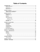
Table of Contents INTRODUCTION................................................................................................................................ 2 Machine Description.................................................................................................................... 2 Contact Info................................................................................................................................. 2 Manual Accuracy......................................................
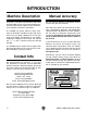
INTRODUCTION Machine Description Manual Accuracy A slip roll is a machine used to flatten and create constant-radius curves in sheet metal workpieces. The three roller system adjusts to allow the operator to complete a number of procedures. We are proud to provide a high-quality owner’s manual with your new machine! The T25688 can quickly adjust to create cone, spiral or continuous cylindrical shapes with sheet metal up to 22 gauge.
Identification B C D E F G A I H Figure 1. Machine identification. Identification List A. Machine Base B. Top Roller C. Rear Roller D. Removable Bushing E. Crank F. Radius Adjustment Knob G. Thickness Adjustment Knob H. Crank Handle I. Bottom Roller E B CCW I G C Sample Illustration F Throughout this manual, diagrams are used to illustrate how the components of the machine are used during the various steps of operation.
MACHINE DATA SHEET Customer Service #: (570) 546-9663 · To Order Call: (800) 523-4777 · Fax #: (800) 438-5901 MODEL T25688 24" SLIP ROLL - 22 GAUGE Product Dimensions: Weight.............................................................................................................................................................. 111 lbs. Width (side-to-side) x Depth (front-to-back) x Height................................................................. 38 x 9-1/2 x 16-1/4 in.
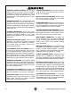
SECTION 1: SAFETY for your Own Safety, Read Instruction Manual before Operating This Machine The purpose of safety symbols is to attract your attention to possible hazardous conditions. This manual uses a series of symbols and signal words intended to convey the level of importance of the safety messages. The progression of symbols is described below. Remember that safety messages by themselves do not eliminate danger and are not a substitute for proper accident prevention measures.
WEaRINg PROPER aPPaREL. do not wear clothing, apparel or jewelry that can become entangled in moving parts. always tie back or cover long hair. Wear non-slip footwear to avoid accidental slips, which could cause loss of workpiece control. hazaRDOuS DuST. dust created while using machinery may cause cancer, birth defects, or long-term respiratory damage. be aware of dust hazards associated with each workpiece material, and always wear a nioSh-approved respirator to reduce your risk. hEaRINg PROTEcTION.
Additional Safety for Slip Rolls OVERLOADING. Overloading this machine can cause injury from flying parts or property damage. Do not exceed the machine capacities. GLOVES AND GLASSES. Always wear leather gloves and approved safety glasses when using the slip roll. SECURING SLIP ROLL. Before using, secure the slip roll to a sturdy vise that is securely fastened to a workbench that can support the weight and dynamic forces involved in forming sheet metal.
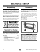
SECTION 2: SETUP Unpacking Inventory Your machine was carefully packaged for safe transportation. Remove the packaging materials from around your machine and inspect it. If you discover any damage, please call us immediately at (570) 546-9663 for advice. The following is a list of items shipped with your machine. Before beginning setup, lay these items out and inventory them. Save the containers and all packing materials for possible inspection by the carrier or its agent.
Cleanup The unpainted surfaces of your machine are coated with a heavy-duty rust preventative that prevents corrosion during shipment and storage. This rust preventative works extremely well, but it will take a little time to clean. Be patient and do a thorough job cleaning your machine. The time you spend doing this now will give you a better appreciation for the proper care of your machine's unpainted surfaces.
Bench Mounting Assembly the base of this machine has mounting holes that allow it to be fastened to a workbench or other mounting surface to prevent it from moving during operation and causing accidental injury or damage. The Model T25688 comes from the factory almost fully assembled. All that is required for assembly is attaching the crank handle to the handle. Thread the crank handle into the small end of the crank and tighten, as shown in Figure 7.
SECTION 3: OPERATIONS Basic Controls To reduce your risk of serious injury, read this entire manual bEfORE using machine. Damage to your eyes and hands could result from using this machine without proper protective gear. Always wear safety glasses Eye hazard! Alwayswhen andinjury leather gloves, wear safety glasses when operating this machine. using this machine. This machine and its components are heavy. Get lifting help to reduce the risk of injury.
Preparation Flat Rolling Before every use, follow these procedures to set up the slip roll for safe, accurate, and efficient use. This slip roll can be used to flat roll sheet metal up to 22 gauge. This can be done to straighten and slightly flatten workpieces. To prepare the slip roll for use: 1. Turn the thickness adjustment knob to lower the bottom roller to approximately 1/4" below the top roller. Use calipers or a spacer to set the distance between the rollers evenly at each end (see Figure 10).
2. Remove the workpiece from between the rollers, then raise the bottom roller slightly by rotating each thickness adjustment knob approximately 1⁄4 turn. Also, make sure the rear roller is lowered completely and will not interfere with the workpiece as it exits the machine (see Figure 12). Creating Bends This slip roll can easily create constant-radius bends in sheet metal up to 22 gauge. Note: The method for creating a specific radius is a trial-and-error process.
2. Turn the crank clockwise to feed the workpiece until its edge is directly above the rear roller, as shown in Figure 15. Figure 15. Feeding the workpiece. 3. Turn the radius adjustment knobs to lift the rear roller until the desired radius bend is reached (see Figure 16). Make sure to turn the knobs equal amounts so the rear roller is always parallel with the other rollers. Failure to do so will create a larger radius on one end than the other, resulting in a cone or spiral shape.
Creating Cylinders This slip roll can be used to easily and accurately create cylinders If you know the diameter of the cylinder you want to create, use the formula below to calculate the length of material needed. C=πD Once you have the necessary length workpiece, follow the steps below to create the cylinder. Note: The method for creating a specific radius is a trial-and-error process.
2. Turn the crank clockwise to feed the workpiece until it is approximately half way through the rollers. 5. Rotate the workpiece 180˚, insert the curved end into the slip roll, then process the workpiece through the machine, as shown in Figures 22–23. 3. Turn the radius adjustment knobs to lift the rear roller until the desired radius bend is reached (see Figure 20). Make sure to turn the knobs equal amounts so the rear roller is always parallel with the other rollers.
6. Continue to process the workpiece until the cylinder is formed, as shown in Figure 24. —If the ends of the cylinder do not meet, lift the rear roller equally at both ends, then process the entire cylinder through the slip roll again. Repeat as necessary. —If the ends of the cylinder overlap, remove the cylinder as described in Removing Workpiece on Page 18. Then, either attempt to increase the radius by manually bending it, or scrap the workpiece.
Removing Workpiece 3. Move the top roller back into position and slide the removable bushing in to secure the top roller (see Figure 28). To remove cylindrical workpieces: 1. Slide the removable bushing outward. This will release the top roller from the stand (see Figure 26). Removable Bushing Removable Bushing Slide In To Secure Figure 28. Securing top roller. Slide Out To Release Figure 26. Removable bushing release. 2. Slide the top roller out from the base (see Figure 27).
ACCESSORIES SECTION 4: ACCESSORIES Installing unapproved accessories may cause machine to malfunction, resulting in serious personal injury or machine damage. To reduce this risk, only install accessories recommended for this machine by grizzly. T23094—Pneumatic Sheet Metal Shear This heavy-duty Pneumatic Sheet Metal Shear provides long life and reliable cutting with an ergonomic grip for comfort and stability. Shears most types of plastics and all types of aluminum, tin, and steel.
SECTION 5 : MAINTENANCE Schedule For optimum performance from the machine, follow this maintenance schedule and refer to any specific instructions given in this section. Daily Check: • Loose mounting bolts. • Any other unsafe condition. Lubrication Roller Gears Lift the gear guard cover and apply a dab of white lithium grease to the upper roller gears (see Figure 32).
SECTION 6: SERVICE Review the troubleshooting and procedures in this section if a problem develops with your machine. If you need replacement parts or additional help with a procedure, call our Technical Support at (570) 546-9663. Note: Please gather the serial number and manufacture date of your machine before calling. Troubleshooting Symptom Possible Cause Possible Solution Slip roll creates cones when trying to create cylinders. 1. Rollers are not parallel. 1.
SECTION 7: PARTS 13 22 23 30 34 29 10 21 33 31 39 9 12 3 27 40 25 20 5 4 6 28 7 15 17 41 16 8 35 37 38 19 36 1 25 24 42 26 14 11 32 2 53 51 54 55 18 57 56 52 REF PART # DESCRIPTION REF PART # DESCRIPTION 1 2 3 4 5 6 7 8 9 10 11 12 13 14 15 16 17 18 19 20 21 22 23 24 25 BASE PLATE SIDE BRACKET (LH) SIDE BRACKET (RH) REAR ROLLER BUSHING LOWER/REAR ROLLER BUSHING (COPPER) ROLLER AXLE SLEEVE REAR ROLLER LOWER ROLLER GEAR SHAFT GEAR 19T GEAR 15T UPPER ROLLER PRESSURE P
WARRANTY CARD Name _____________________________________________________________________________ Street _____________________________________________________________________________ City _______________________ State _________________________ Zip _____________________ Phone # ____________________ Email _________________________________________________ Model # ____________________ Order # _______________________ Serial # __________________ The following information is given on a voluntary basis.
FOLD ALONG DOTTED LINE Place Stamp Here GRIZZLY INDUSTRIAL, INC. P.O.
WARRANTY & RETURNS Grizzly Industrial, Inc. warrants every product it sells for a period of 1 year to the original purchaser from the date of purchase. This warranty does not apply to defects due directly or indirectly to misuse, abuse, negligence, accidents, repairs or alterations or lack of maintenance.