
Instruction Manual
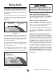

Operation Overview
To complete a typical operation, the operator
does the following:
1.
2.
3.
4.
5.
6.
7.
8.
9.
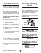
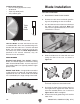
Disabling & Locking
Switch
Figure 34.
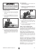
The switch can be disabled and locked by insert-
ing a padlock through the ON/START button, as
shown. Locking the switch in this manner can
prevent unauthorized operation of the machine,
which is especially important if the machine is not
stored inside an access-restricted building.
IMPORTANT: Locking the switch with a padlock
only restricts its function. It is not a substitute
for disconnecting power from the machine when
adjusting or servicing.
Shaft
Padlock
ON / START
Button
OFF / STOP
Paddle
Figure 33.
NOTICE
The padlock shaft diameter is important to
the disabling function of the switch. With
any padlock used to lock the switch, test
the switch after installation to ensure that it
is properly disabled.
Children or untrained people can be
seriously injured by this machine. This
risk increases with unsupervised operation.
To help prevent unsupervised operation,
disable and lock the switch before leaving
machine unattended! Place key in a well-
hidden or secure location.