MODEL G0605X1/G0606X1/ G0696X/G0697X 12" LEFT TILTING TABLE SAW OWNER'S Manual Model G0697X 175370 Model G0606X1 Copyright © FEBRUARY, 2009 By Grizzly Industrial, Inc. revised AUGUST, 2011 (TR) Warning: No portion of this manual may be reproduced in any shape Or form without the written approval of Grizzly Industrial, inc.
This manual provides critical safety instructions on the proper setup, operation, maintenance, and service of this machine/tool. Save this document, refer to it often, and use it to instruct other operators. Failure to read, understand and follow the instructions in this manual may result in fire or serious personal injury—including amputation, electrocution, or death. The owner of this machine/tool is solely responsible for its safe use.
Table of Contents INTRODUCTION................................................ 2 Manual Accuracy............................................ 2 Contact Info.................................................... 2 Machine Description....................................... 2 Identification.................................................... 3 Machine Data Sheets..................................... 4 SECTION 1: SAFETY........................................ 5 Safety Instructions for Machinery...................
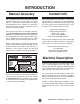
INTRODUCTION Manual Accuracy Contact Info We are proud to offer this manual with your new machine! We've made every effort to be exact with the instructions, specifications, drawings, and photographs of the machine we used when writing this manual. However, sometimes we still make an occasional mistake. We stand behind our machines. If you have any questions or need help, use the information below to contact us. Before contacting, please get the serial number and manufacture date of your machine.
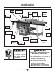
Identification Miter Gauge Blade Guard & Spreader Front Rail Tube Outfeed Table Fence Lock Handle Fence Scale Indicator On/Off Switch Fence Front Extension Table Front Rail Switch Disabling Lock Support Leg Motor Cover Blade Height Handwheel Blade Tilt Scale Blade Height Lock Blade Angle Digital Readout Blade Tilt Handwheel & Lock Figure 1. G0606X1 identification.
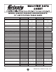
MODEL G0605X1/G0606X1/G0696X/G0697X 12" LEFT-TILTING TABLE SAWS Model Number G0605X1 G0606X1 G0696X G0697X 5 HP, 220V, 1-Ph 71⁄2 HP, 220V/440V, 3-Ph 5 HP, 220V, 1-Ph 71⁄2 HP, 220V/440V, 3-Ph 30 Amps 30 Amps @220V 15 Amps @440V 30 Amps 30 Amps @220V 15 Amps @440V 3450 RPM 3450 RPM 3450 RPM 3450 RPM 220V, 1-Ph, 60 Hz 220V/440V, 3-Ph, 60 Hz 220V, 1-Ph, 60 Hz 220V/440V, 3-Ph, 60 Hz 18 19.5/10 18 19.
SECTION 1: SAFETY For Your Own Safety, Read Instruction Manual Before Operating this Machine The purpose of safety symbols is to attract your attention to possible hazardous conditions. This manual uses a series of symbols and signal words intended to convey the level of importance of the safety messages. The progression of symbols is described below. Remember that safety messages by themselves do not eliminate danger and are not a substitute for proper accident prevention measures.
DISCONNECTING POWER SUPPLY.Alwaysdisconnect machine from power supply before servicing, adjusting, or changing cutting tools (bits, blades, cutters, etc.). Make sure switch is in OFF positionbeforereconnectingtoavoidanunexpectedorunintentionalstart. APPROVED OPERATION. Untrained operators can be seriously hurt by machinery. Only allow trained or properly supervised people to use machine.
Additional Safety for Table Saws HAND POSITIONING. Never purposely touch a saw blade during operation. Always keep hands/ fingers out of the blade path; place them where they cannot slip into the blade accidentally. Never reach around, behind, or over the blade. Touching a spinning saw blade will cause serious laceration or amputation injuries. BLADE GUARD. Use the blade guard for all “through cuts” for which it can be used.
Preventing Kickback Take the precautions below to avoid the most common causes of kickback: • Only cut workpieces with at least one smooth and straight edge. DO NOT cut warped, cupped or twisted wood. • Never move the workpiece backwards or try to back it out of a cut while the blade is moving. If you cannot complete a cut for some reason, stop the saw motor and allow the blade to completely stop before backing the workpiece out.
Glossary of Terms The following is a list of common definitions, terms and phrases used throughout this manual as they relate to this table saw and woodworking in general. Become familiar with these terms for assembling, adjusting or operating this machine. Your safety is VERY important to us at Grizzly! Arbor: A metal shaft extending from the drive mechanism that is the mounting location for the saw blade.
SECTION 2: POWER SUPPLY Availability Circuit Information Before installing the machine, consider the availability and proximity of the required power supply circuit. If an existing circuit does not meet the requirements for this machine, a new circuit must be installed. To minimize the risk of electrocution, fire, or equipment damage, installation work and electrical wiring must be done by a qualified electrician in accordance with all applicable codes and standards.
Model G0606X1/G0697X Circuit Requirements for 440V Model G0606X1/G0697X Connection Device This machine can be converted to operate on a 440V power supply (refer to Voltage Conversion instructions) that has a verified ground and meets the following requirements: For 220V operation: The power cord and plug specified under “Circuit Requirements for 220V” on the previous page have an equipment-grounding wire and a grounding prong.
Correcting Phase Polarity Grounding Instructions Check with a qualified electrician or service personnel if you do not understand these grounding requirements, or if you are in doubt about whether the tool is properly grounded. If you ever notice that a cord or plug is damaged or worn, disconnect it from power, and immediately replace it with a new one. Extension Cords (220V Only) We do not recommend using an extension cord with this machine.
Voltage Conversion 4. Rewire the motor, as shown in Figure 7, tighten the hex nuts, then re-install the junction box cover. The Model G0606X1/G0697X can be converted for 440V operation. Ground This conversion job consists of disconnecting the saw from the power source, rewiring the motor, switching the transformer fuse from 220V to 440V, and changing the thermal overload relay from 22 to 11 Amps. U1 W1 W2 Y1 V2 U2 X1 V1 Z1 NOTICE Figure 7. Motor rewired to 440V.
SECTION 3: SETUP Needed for Setup This machine presents serious injury hazards to untrained users. Read through this entire manual to become familiar with the controls and operations before starting the machine! Wear safety glasses during the entire setup process! This machine and its components are very heavy. Get lifting help or use power lifting equipment such as a forklift to move heavy items.
Hardware Recognition Chart G0605X1-6X1, G0696X-97X (Mfg.
G0605X1/G0606X1 Inventory The following is a description of the main components shipped with your machine. Lay the components out to inventory them. If any non-proprietary parts are missing (e.g. a nut or a washer), we will gladly replace them; or for the sake of expediency, replacements can be obtained at your local hardware store. NOTICE If you cannot find an item on this list, check the mounting location on the machine or the packaging materials.
Extension Table Inventory Outfeed Table Inventory Box Contents: (Figure 14) Qty A. Extension Table........................................... 1 B. Lower Shelf................................................. 1 C. Shelf End Plate............................................ 1 D. Support Legs............................................... 2 E. Lower Shelf Brackets.................................. 2 Box Contents: (Figure 15) Qty A. Outfeed Table . ............................................ 1 B.
Fence Box Contents: (Figure 19) Qty A. Fence .......................................................... 1 B. Fence Handle.............................................. 1 B A A Figure 16. G0696X table saw unit. B C Figure 19. Fence components. D Fence Rail Inventory L H E G I Box Contents: (Figure 20) Qty A. Fence Tube (75" Long)................................ 1 B. Front Rail (75" Long)................................... 1 C. Rear Rail (621⁄ 2" Long).................................
Cleanup The unpainted surfaces of your machine are coated with a heavy-duty rust preventative that prevents corrosion during shipment and storage. This rust preventative works extremely well, but it will take a little time to clean. Be patient and do a thorough job cleaning your machine. The time you spend doing this now will give you a better appreciation for the proper care of your machine's unpainted surfaces.
Site Considerations Weight Load Physical Environment Refer to the Machine Data Sheet for the weight of your machine. Make sure that the surface upon which the machine is placed will bear the weight of the machine, additional equipment that may be installed on the machine, and the heaviest workpiece that will be used. Additionally, consider the weight of the operator and any dynamic loading that may occur when operating the machine.
Assembly 3. Assembly steps are the same for all models except where noted. Assembly consists of installing the front and rear rails, attaching the extension wing (Model G0696X/G0697X) or extension table and outfeed table (Model G0605X1/G0606X1), then installing minor components. Fasten the rear rail to the table with (4) M8-1.25 x 25 cap screws, 8mm lock washers, and 8mm flat washers, as shown in Figure 23. Extension Wing To assemble the table saw: 1.
2. With the assistance of a helper, place the extension wing between the rails, and fasten the wing to the front rail with (1) M8-1.25 x 25 flat head screw, 8mm lock washer and M8-1.25 hex nut (see Figure 24). Finger tighten for now. Front Rail Rear Rail Lock Cap Washers Screw Hex Flat Nuts Lock Washer Washer Flat Head Screw 5. Use a straightedge as a gauge and adjust the extension wing up/down until it is flush with the main table above each bolt, then completely tighten all the bolts. 6.
G0605X1/G0606X1 Extension Table 4. 1. Thread (2) M10-1.5 x 25 hex bolts with 10mm flat washers onto the right side of the main table, as shown in Figure 28. Do not fully tighten the bolts. Fasten the rear rail to the extension table with (3) M8-1.25 x 25 cap screws, (3) 8mm lock washers, (6) 8mm flat washers, and (3) M8-1.25 hex nuts, as shown in Figure 30. Finger tighten the hex nuts for now. x3 x2 Figure 30. Rear rail/table fastener locations. 5. Figure 28. Hex bolts installed. 2.
7. Fasten the support legs to the main extension table with (8) M6-1 x 12 Phillips head screws and 6mm flat washers (see Figure 33). Shelf Bracket Flange x2 x8 Figure 33. Support leg fastened to main extension table. 8. Rotate both feet until they touch the ground, and tighten the hex nuts against the legs to secure the feet. 9. Fasten the shelf end plate to the legs with (4) M6-1 x 12 Phillips head screws and 6mm flat washers, as shown in Figure 34. x2 Figure 35. Shelf brackets installed.
6. Place the 913/8" fence tube over the 911/4" front rail, secure with (9) M8-1.25 x 12 flange bolts, as shown in Figure 37, then install the handwheel handles. 2. Turn the insert so shown in and set it lock knob that secures the table it is parallel to the inner slot, as Figure 39, then remove the insert aside. Handwheel Handles Lock Knob x9 Figure 37. Fence tube mounted to front fence rail. Figure 39. Insert lock knob unlocked. On/Off Switch and Blade 1.
Dust Collection 6. Install the fence knob as shown in Figure 41, and mount the fence on the front rail, to the right of the blade. DO NOT operate the Model G0605X1/ G0606X1/G0696X/G0697X without an adequate dust collection system. This saw creates substantial amounts of wood dust while operating. Failure to use a dust collection system can result in short and long-term respiratory injury. Fence Knob Figure 41. Fence knob installed. 7.
Power Connection Before the machine can be connected to the power source, an electrical circuit must be made available that meets the minimum specifications given in "Circuit Requirements for 220V" on Page 10. If a power circuit has not been prepared for the machine, do that now. To ensure a safe and codecompliant setup, we strongly recommend that all electrical work be done by a qualified electrician. G0605X1/G0606X1/G0696X/G0697X 220V Power Connection 1.
Test Run 8. Insert the switch disabling lock through the green ON button, as shown in Figure 48. Test run your machine to make sure it runs properly and is ready for regular operation. The test run consists of verifying the following: 1) The motor powers up and runs correctly, 2) the safety disabling mechanism on the switch works correctly, and 3) the blade turns the correct direction (the machine is not wired out of phase— G0606X/G0697X only).
Final Setup The remaining tasks required for assembling the saw include the following steps: installing the table insert and cutting a slot for the blade, checking fence parallelism, installing the blade guard, and calibrating the blade angle digital readout. To complete the remaining assembly steps: 1. DISCONNECT SAW FROM POWER! 2. Install and cut the table insert, as instructed in Cutting a Zero Clearance Insert on Page 39, then proceed to the next step. 3.
SECTION 4: OPERATIONS Basic Controls Damage to your eyes, lungs, and ears could result from using this machine without proper protective gear. Always wear safety glasses, a respirator, and hearing protection when operating this machine. ON/OFF Switch: Starts and stops motor. Switch Disabling Lock: This disables the switch to prevent accidental startup and restrict usage. Padlock Shaft ON / START Button Loose hair, clothing, or jewelry could get caught in machinery and cause serious personal injury.
Operation Overview The purpose of this overview is to provide the novice machine operator with a basic understanding of how the machine is used during a typical operation, so the controls/components discussed later in this manual are easier to understand. Due to the generic nature of this overview, it is not intended to be an instructional guide. To learn more about specific operations, read this entire manual, read "how to" books, and seek additional training from experienced machine operators.
Non-Through & Through Cuts Non-Through Cuts A non-through cut is a sawing operation where the blade does not protrude above the top face of the wood stock, as shown in the Figure below. Figure 53. Example of a non-through cut. Examples of non-through cuts include dadoes and rabbets. Non-through cuts have a higher risk of injury from kickback because the blade guard must be removed. However, the riving knife MUST be installed because it still provides some protection.
Blade Requirements The spreader/riving knife included with this machine is 0.09" (2.3mm) thick and is only designed for 12" diameter blades. When choosing a main blade, make sure the blade size meets the requirements listed below. The thickness of the blade body and teeth can be measured with calipers or any precision measuring device. Blade Size Requirements: • Body Thickness: 0.074"–0.082" (1.9mm–2.1mm) • Kerf (Tooth) Thickness: 0.114"–0.122" (2.9mm–3.
Laminate blade features: • Best for cutting plywood or veneer • 40-80 teeth • Triple chip tooth profile • Very shallow gullet Blade Installation To install a new blade: 1. DISCONNECT SAW FROM POWER! 2. Remove the table insert and blade guard/riving knife, depending on what is installed. Triple Chip Blade 3. Use the arbor wrenches to loosen and remove the arbor nut, flange, and blade. Note: The arbor nut has right hand threads; turn it counterclockwise to loosen. Figure 58. Laminate blade.
Blade Guard Assembly The term "blade guard" refers to the assembly that consists of the clear polycarbonate shield, the spreader, and the anti-kickback pawls on each side of the spreader (Figure 62). Each of these components has important safety functions. Clear Shield In order to work properly, the spreader cannot be bent or misaligned with the blade. If the spreader gets accidentally bent, take the time to straighten it or just replace it.
The blade guard, when properly installed, should look like Figure 64 and should pivot freely so it touches the table surface in the down position. It should also swing up high enough to accommodate the workpiece. — If the spreader/riving knife is not inside the alignment zone and not parallel with the blade, then it needs to be adjusted. Proceed to "Adjusting Alignment" on Page 68. — If the spreader/riving knife is not parallel with the blade, it may be bent.
We do not recommend removing the pawls during normal operations unless absolutely necessary. In most situations, removing the pawls will increase your risk of serious personal injury in the event of kickback. Re-installing Pawls 1. Loosen the knob on top of the spreader, then remove the blade guard. 2. Slide the pin in the pawl block into the second groove from the front of the spreader, as shown in Figure 68. Groove To remove the pawls: 1.
Riving Knife The riving knife works in the same manner as the spreader on the blade guard assembly. It is a metal plate that prevents the newly cut workpiece from pinching the backside of the blade and causing kickback. The key difference between the spreader and the riving knife is that the riving knife mounts below the blade's highest point of rotation, as shown in Figure 69. Minimum 1mm Maximum 5mm Height Difference Figure 69. Height difference between riving knife and blade.
Cutting a Zero Clearance Insert Clamps A zero clearance insert is provided with the table saw to reduce workpiece tear out and increase user safety. The insert can be customized to fit a specific blade height or blade angle for the applicable cutting operation. Insert 2" Thick Board Figure 72. Securing insert with board and clamps. To install the zero clearance insert: 1. DISCONNECT SAW FROM POWER! 2.
Ripping "Ripping" means cutting with the grain of a natural wood workpiece. In man-made materials such as MDF or plywood, ripping simply means cutting lengthwise. 10. Use a push stick to feed the workpiece through the saw blade, as shown in Figure 73, until the workpiece is completely beyond the saw blade. Serious injury can be caused by kickback. Kickback is a high-speed expulsion of stock from the table saw toward an operator.
Crosscutting Miter Cuts "Crosscutting" means cutting across the grain of a natural wood workpiece. In man-made materials, such as MDF or plywood, crosscutting means cutting across the width of the workpiece. A miter is an angled crosscut. Miters are usually cut in the same manner as crosscuts, using the miter gauge and a predetermined mark on the workpiece. To make a crosscut using the miter gauge: To perform a miter cut: 1. DISCONNECT SAW FROM POWER! 1. DISCONNECT SAW FROM POWER! 2.
Blade Tilt/Bevel Cuts When the blade tilt stop bolts are properly adjusted (as described on Page 64), the blade tilt handwheel allows the operator to tilt the blade to the left, between 0° and 45°. This is used most often when cutting bevels, compound miters or chamfers. Figure 76 shows an example of the blade when tilted to 45°. Figure 76. Blade tilted to 45° for bevel cutting on a typical table saw.
Cutting Dadoes with a Dado Blade To cut a dado with a dado blade: The Figure below demonstrates the sequential process of making multiple, light cuts that get progressively deeper. The actual number of cuts used should be determined by workpiece hardness, total dado depth, and feed rate. In general, if you hear the motor slow down during the cut, you are cutting too deep or feeding too fast. 1. Adjust the dado blade to the desired depth of cut. 2.
Cutting Dadoes with Standard Blade A ripping blade (described on Page 33) is typically the best blade to use for cutting dadoes when using a standard blade, because it removes sawdust very efficiently. To use a standard saw blade to cut dadoes: 1. DISCONNECT SAW FROM POWER! 2. Ensure that the riving knife and standard table insert are installed and properly adjusted.
Rabbet Cutting Commonly used in furniture joinery, a rabbet is an L-shaped groove cut in the edge of the workpiece. Rabbets can be cut with either a dado blade or a standard saw blade. Rabbet cutting on the edge of the workpiece with a dado blade requires a sacrificial fence (Figure 82). Make the sacrificial fence the same length as the fence and 3⁄4" thick. Attach it to the fence with screws or clamps, making sure they are all secure and tight.
Cutting Rabbets with a Standard Blade A ripping blade is typically the best blade to use for cutting rabbets when using a standard blade because it removes sawdust very efficiently. (See Page 33 for blade details.) Also, a sacrificial fence is not required when cutting rabbets with a standard blade. To cut rabbets with the standard blade: 1. DISCONNECT SAW FROM POWER! 2. Ensure that the riving knife and standard table insert are installed. 3.
Resawing Resawing operations require proper procedures to avoid serious injury. Extra care must be taken to prevent kickback when resawing. Any tilting or movement of the workpiece away from the fence will cause kickback. Be certain that stock is flat and straight. Failure to follow these warnings could result in serious personal injury. Resawing is the process of cutting a thick piece of stock into one or more thinner pieces.
Auxiliary Fence The auxiliary fence is necessary if you are resawing a workpiece that is taller than it is wide. It should be no less than 1⁄2" shorter than the board to be resawn. Fence Facing Components Needed for the Auxiliary Fence: Wood* 3⁄4" x (Height) x Length of Fence.............1 Flat Head Screws M8-1.25 x 25 (Not included)..4 Hex Nuts M8-1.25 (Included)..............................4 Flat Washers 8mm (Included).............................
4. Attach the auxiliary fence to the standard fence and set it to the desired width. Note: When figuring out the correct width, don't forget to account for blade kerf and the inaccuracy of the fence scale while the auxiliary fence is installed. 5. Place the workpiece against the auxiliary fence and slide the resaw barrier against the workpiece, as shown in Figure 88. Now clamp the resaw barrier to the table at both ends.
SECTION 5: SHOP MADE SAFETY ACCESSORIES Featherboards Easily made from scrap stock, featherboards provide an added degree of protection against kickback, especially when used together with push sticks. They also maintain pressure on the workpiece to keep it against the fence or table while cutting, which makes the operation easier and safer because the cut can be completed without the operator’s hands getting near the blade.
4. Rout a 1⁄4"–3⁄8" wide slot 4"–5" long in the workpiece and 1"–2" from the short end of the featherboard (see Figure 91). /4"-3/8" Slot 1 1"-2" 6. Drill a 1⁄4" hole in the center of the bar, then countersink the bottom to fit a 1⁄4"-20 flat head screw. 7. Mark a 4" line through the center of the countersunk hole, then use a jig saw with a narrow blade to cut it out. 8. 4"-5" Figure 91. Slot routed in featherboard. 5.
Mounting Featherboards w/Clamps Mounting Featherboard in Miter Slot 1. Lower the saw blade, then adjust the fence to the desired width and secure it. 1. Lower the saw blade, then adjust the fence to the desired width and secure it. 2. Place the workpiece against the fence, making sure it is 1" in front of the blade. 2. Place the workpiece evenly against the fence, making sure it is 1" in front of the blade. 3.
Push Sticks Supporting: A second push stick can be used to keep the workpiece firmly against the fence while cutting. When using a push stick in this manner, only apply pressure before the blade; otherwise, pushing the workpiece against or behind the blade will increase the risk of kickback (see "Push Stick Prohibition Zone" in the Figure below). When used correctly, push sticks reduce the risk of injury by keeping hands away from the blade while cutting.
Push Blocks The notched end of the push block is then used to push the workpiece the rest of the way through the cut, keeping the operator's hands at a safe distance from the blade. A push stick is often used at the same time in the other hand to support the workpiece during the cut (see "Using a Push Stick" on previous page). When used correctly, a push block reduces the risk of injury by keeping hands away from the blade while cutting.
Narrow-Rip Auxiliary Fence & Push Block There are designs for hundreds of specialty jigs that can be found in books, trade magazines, and on the internet. These types of jigs can greatly improve the safety and consistentcy of cuts. They are particularly useful during production runs when dozens or hundreds of the same type of cut need to be made.
Using the Auxiliary Fence and Push Block 1. Place the auxiliary fence on the table and clamp it to the fence at both ends, then adjust the distance between the auxiliary fence and the blade—this determines how wide the workpiece will be ripped (see Figure 105). 3. Place the workpiece 1" behind the blade and evenly against the table and the auxiliary fence. Auxilliary Fence Blade Workpiece Auxilliary Fence Push Stick for Side Support Push Block Blade Blade Path Workpiece Cutting Width Figure 105.
Outfeed & Support Tables One of the best accessories for improving the safety and ease of using a table saw is simply placing a large table (outfeed table) behind the saw to catch the workpiece (see Figure 108). Additionally, another table to the left of the saw (support table) can also help support large workpieces so they can be cut safely and accurately. Support Table Crosscut Sled A crosscut sled (see Figure 109) is a fantastic way to improve the safety and accuracy of crosscutting on the table saw.
ACCESSORIES SECTION 6: AFTERMARKET ACCESSORIES FROM GRIZZLY Some aftermarket accessories can be installed on this machine that could cause it to function improperly, increasing the risk of serious personal injury. To minimize this risk, only install accessories recommended for this machine by Grizzly.
H8875—26" Wide Outfeed Roller System G1317—37" Wide Outfeed Roller System These unique roller systems fold down easily without tools and snap up in place quickly when needed. Both units have a double level system which lets you set the rollers either in line with the table or slightly below it. Figure 113. Outfeed roller system. G5562—SLIPIT 1 Qt. Gel G5563—SLIPIT® 12 oz Spray G2871—Boeshield® T-9 12 oz Spray G2870—Boeshield® T-9 4 oz Spray H3788—G96 ® Gun Treatment 12 oz Spray H3789—G96 ® Gun Treatment 4.
SECTION 7: MAINTENANCE Cleaning Always disconnect power to the machine before performing maintenance. Failure to do this may result in serious personal injury. Schedule For optimum performance from your machine, follow this maintenance schedule and refer to any specific instructions given in this section. Daily Check: • Inspect blades for damage or wear. • Check for loose mounting bolts/arbor nut. • Check cords, plugs, and switch for damage.
Lubrication It is essential to clean components before lubricating them because dust and chips build up on lubricated components and make them hard to move. Simply adding more grease to them will not yield smooth moving components. Worm Gear, Bevel Gears, Mounting Plate Teeth and Check every month. Use a wire brush and mineral spirits to clean away any built up grime and debris from the worm gear, bevel gear, and mounting plate teeth (see Figure 118).
Troubleshooting SECTION 8: SERVICE Review the troubleshooting and procedures in this section if a problem develops with your machine. If you need replacement parts or additional help with a procedure, call our Technical Support at (570) 546-9663. Note: Please gather the serial number and manufacture date of your machine before calling. Troubleshooting Symptom Motor start. does Possible Cause Possible Solution 1. Remove switch disabling lock. 2.
Symptom Possible Cause Possible Solution Handwheel binds or 1. Lock knob is engaged. is difficult to move. 2. Handwheel shaft pins are wedged. 3. Handwheel is inserted too far. 4. Too much engagement between the worm gear & trunnion 1. Loosen lock knob. 2. Remove handwheel and adjust shaft pins. 3. Remove handwheel and adjust key. 4. Adjust worm gear engagement. Blade does not 1. Pointer or scale calibrated incorrectly. reach 90 degrees. 1. Calibrate pointer/scale at true 90 degrees (see Page 64). 2.
Blade Tilt Stops The table saw features bolts that stop the blade tilt exactly at 45° and 90° when using the handwheel. These stops have been set at the factory and should require no adjustments, unless you notice that your cuts are not accurate. Adjust the indicator position by loosening the Phillips head screw, moving the indicator, then tightening the screw and re-installing the handwheel. Proceed to Setting 45º Stop Bolt on Page 65. Note: The tilt scale reads "0" when the blade is 90° to the table.
—If the blade is 45° to the table, then adjustments do not need to be made. 90° Stop Bolt & Jam Nut —If the blade is not 45° to the table, you will need to adjust the 45° stop screw. Proceed to the next step. 4. Tilt the blade to 20°, so there is room for the stop bolt to move. 5. Loosen the jam nut on the 45° stop bolt (see Figure 125) with a 13mm wrench, then adjust the stop bolt up or down according to how far off the blade was from 45°. Figure 123.
Miter Slot to Blade Parallelism 6. Compare the distance from the marked blade tip to the miter slot, as shown in Figure 127. STEP B Your table saw will give the best results if the miter slot is parallel with the blade. If these components are not exactly parallel with each other, your cuts and your finished work will be lower in quality, but more importantly, the risk of kickback will be increased. Tools Needed Qty Adjustable Square.............................................. 1 Metal Shim Stock.......
8. Tilt the blade to 45° and repeat Steps 3–6. —If the blade is still parallel with the miter slot, continue onto the Blade Alignment procedure. —If the blade was parallel with the miter slot at 90° but not at 45°, one end of the table will need to be shimmed higher with metal shim stock. 9. 11. Tighten one bolt a small amount and then repeat with the others, tightening each down the same amount. Continue this process with all the bolts, tightening them a little each time until they are all secure. 12.
Spreader or Riving Knife Alignment Spreader or Riving Knife Checking Alignment The blade guard spreader and riving knife must be aligned with the blade when installed. If the spreader/riving knife is not aligned with the blade, then the workpiece will before forced sideways during the cut, which will increase the risk of kickback. Tools Needed Qty Straightedge....................................................... 1 To check the spreader/riving knife alignment: 1. DISCONNECT SAW FROM POWER! 2.
Adjusting Alignment 4. The spreader/riving knife mounts to a block that can be repositioned to correctly align the spreader/riving knife to the blade. The mounting block adjusts by turning the set screws in each corner of the block. Tighten the lock knob (see Figure 134), then re-install the table insert. Lock Knob Figure 133 shows the set screws associated with controlling the mounting block position. Side Control Side Control Mounting Block Top Control Bottom Control Figure 134.
Fence Adjustments 3. Adjust the set screws (Figure 136) on top of the fence bracket to ensure the fence face is 90° to the table. There are four main adjustments for the fence: 1) square, (2) height, (3) parallelism, and (4) clamping pressure.. Keep in mind that these adjustments are interconnected and some trial-and-error may be needed to achieve satisfactory results. Set Screws Rear Rail Foot Tools Needed Qty Hex Wrench 4mm............................................... 1 Hex Wrench 6mm.............
Note: If the front end of the fence needs to be adjusted up or down, use the set screws from Figure 136; however, turn them in even increments and recheck the squareness afterwards. — If the fence and miter slot are parallel with the blade, as shown in Figure 138, no further adjustments need to be made. Clamping Pressure and Parallelism — If the fence is not parallel with the blade/ miter slot, then you must adjust the fence parallel with the blade.
Fence Scale Calibration 5. Rotate the blade 180° and recheck the distance between the fence and the blade tooth you marked in Step 4 to ensure they are parallel (see Figure 138 on Page 71). 6. Use trial-and-error to adjust the set screws so the fence is parallel to the blade and the clamping pressure is sufficient. Offsetting Fence Some woodworkers prefer to offset the rear of the fence 1/64" from the blade, as shown in Figure 140.
Miter Gauge Adjustments 4. Place the 90° square evenly against the face of the miter gauge and the blade, as shown in Figure 143. — If the square touches the miter body and the body of the blade (not the teeth) evenly at the same time, then it is square to the blade and the 90° stop is set correctly. No further adjustments are necessary. The miter gauge is equipped with stop screws that allow you to easily adjust the miter gauge from 45° to the left, 90°, and 45° to the right (see Figure 142).
Table Tilt Handwheel Backlash Digital Readout Calibration The table tilt handwheel should move with very little backlash or slop when the saw is new. Over time the tilt gears may wear, increasing backlash. You can eliminate backlash by adjusting the tilt handwheel gears. The digital readout displays the current blade angle. Only set the readout after verifying that the 90° and 45° blade tilt stops are correctly positioned. Tools Needed Qty Hex Wrench 6mm...............................................
Belt Tension & Replacement Wood Block The belt stretches slightly as the saw is used. Most of the belt stretching will happen during the first 16 hours of use, but it may continue to gradually stretch with continued use. To ensure optimum power transmission from the motor to the blade, the belt must be in good condition. Replace the belt if it becomes cracked, frayed, or glazed. Tools Needed Qty Arbor Wrenches................................................. 2 Wood Block 10" Long 4x4 .....................
Replacing Belt 1. DISCONNECT SAW FROM POWER! 2. Raise the motor all the way up, tilt it to 0°, and open the motor cover. 3. Loosen the four motor mounting hex nuts (Figure 147) two turns, and place the 2x6 block between the cabinet and bottom of the motor, as shown in Figure 150. Belt Motor Pulley Figure 151. Removing belt (table removed for clarity). 8. Turn the new belt sideways and slip it over the motor pulley, as shown in Figure 152, so it engages one or two grooves.
machine SECTION 9: WIRING These pages are current at the time of printing. However, in the spirit of improvement, we may make changes to the electrical systems of future machines. Compare the manufacture date of your machine to the one stated in this manual, and study this section carefully. If there are differences between your machine and what is shown in this section, call Technical Support at (570) 546-9663 for assistance BEFORE making any changes to the wiring on your machine.
Common Electrical Components Figure 154. G0605X1/G0696X motor junction box. Figure 157. Digital readout and angle sensor. Figure 155. On/Off switch. Figure 156. G0606X1/G0697X motor junction box. -78- READ ELECTRICAL SAFETY ON PAGE 77! Figure 158. G0605X1/G0696X magnetic switch. G0605X1-6X1, G0696X-97X (Mfg.
G0605X1/G0696X Wiring 220V, 1-Ph Power Junction Box L6-30 Plug (As Recommended) Ground Hot X G A R/1/L1 S/3/L2 T/5/L3 Y Hot Ground NO13 220 VAC SDE MA-30 NC15 NC16 Magnetic Switch Assembly MPE-30 220V U/2/T1 V/4/T2 W/6/T3 NO14 See Figure 158, Page 78 1/2 3/4 5/6 RESET SDE RA-30 OFF B 18 26 98 96 Digital Readout See Figure 157, Page 78 22 95 AC1 AC2 R18 Installation work and electrical wiring must be done by qualified electrician in accordance with all applicable codes and
G0606X1/G0697X Electrical Components Figure 159. G0606X1/G0697X magnetic switch prewired to 220V, 3-phase. Figure 160. G0606X1/G0697X magnetic switch converted to 440V, 3-phase. Note: The thermal relay in Figure 159 is set for 20 amp, 220V, 3-phase operation. Note: The therrmal relay in Figure 160 is adjusted for 10 amp, 440V, 3-phase operation. -80- READ ELECTRICAL SAFETY ON PAGE 77! G0605X1-6X1, G0696X-97X (Mfg.
G0606X1/G0697X Wiring 220V, 3-Ph Hot Power Junction Box Ground Hot 220 VAC Hot L15-30 PLUG (as recommended) PHASE CONVERTER Ground If connecting machine to a phase converter, the manufactured leg must be connected to terminal L3. A T/5/L3 NO13 440V S/3/L2 220V R/1/L1 SDE MA-30 NC15 NC16 220V U/2/T1 V/4/T2 W/6/T3 NO14 Installation work and electrical wiring must be done by qualified electrician in accordance with all applicable codes and standards.
G0606X1/G0697X Wiring 440V, 3-Ph Power Junction Box Ground 3-PHASE 440 VAC Hot Hot DISCONNECT SWITCH (as recommended) Hot Ground A T/5/L3 NO13 SDE MA-30 NC15 440V S/3/L2 220V R/1/L1 NC16 220V U/2/T1 V/4/T2 W/6/T3 Installation work and electrical wiring must be done by qualified electrician in accordance with all applicable codes and standards.
SECTION 10: PARTS Motor and Arbor 6 G0606X1 & G0697X 6-3 6-1 7-1/2 HP 3-PH 220/440V 6-2 MOTOR 6 G0605X1 & G0696X 6-3 6-1 5PH 1-PH 220V 6-2 MOTOR 6-8 6-4 6-6 6-5V2 6-7V2 126 127 128 158 129 130 131 5 11 13 14 13 12 15 61 29 27 31 32 33 34 35 46 47 124 48 38 37 36 42 38 43 44 45 49 8 22 23 25 24 17V2-9 17V2-8 17V2-7 17V2-6 17V2-2 17V2-5 17V2-3 15 38 17V2-4 67 20 21 134 68 135 69 65 133 27 71 18 65 70 66 25 40 72 27 63 39 40 39 41 99 64 55 38 57 27 5HP 220V 17V2-10 17V2-
Motor and Arbor Parts List REF PART # DESCRIPTION REF PART # 5 7 8 9 10 11 12 13 14 15 16 17V2 17V2-1 17V2-2 17V2-3 17V2-4 17V2-5 17V2-6 17V2-7 17V2-8 17V2-9 17V2-10 18 19 20 21 22 23 24 25 26 27 28 29 30 31 32 33 34 35 36 37 38 39 40 41 42 43 44 P0605X137 PN02M PW04M PLW06M P0605X113 PK02M PSS03M P0605X1013 P0605X1014 P6005-2RS PFB15M P0605X1017V2 P0605X1017V2-1 PCAP14M P0661044V2-3 P0661044V2-4 P0605X1017V2-5 PBHS06M PLW01M P0661044V2-8 PBHS16M PSS112M PCAP14M P0605X1019 P0605X1020 P0605X1021 P0605X
G0605X1/G0696X 5HP,MOTOR 1-PH MOTOR G0605X1 & G0696X 5HP, 1-PHASE REF PART # DESCRIPTION G0605X1 & G0696X 5HP, 1-PHASE MOTOR 6 P0605X1006 MOTOR 5HP 220V 1-PH REF PART # DESCRIPTION 6-1 P0605X1006-1 MOTOR FAN COVER 6 P0605X1006 MOTOR 5HP 220V 1-PH 6-2 P0605X1006-2 MOTOR FAN 6-1 P0605X1006-1 MOTOR FAN COVER 6-3 P0605X1006-3 WIRING JUNCTION BOX 6-2 P0605X1006-2 MOTOR FAN 6-4 P0605X1006-4 R CAPACITOR COVER 6-3 P0605X1006-3 WIRING JUNCTION BOX 6-5V2 P0605X1006-5V2 R CAPACITOR 35M 450V V2.08.
Cabinet 103V2 103V2-3 150 103V2-5 103V2-1 103V2-2 9 39 101 110 103V2-4 103V2-6 103V2-7 103V2-8 G0696X & G0697X ONLY 73 152 5 74 94 76 75 98 8 9 96 I 100 95 92 93 55 55 9 7 8 9 96 8 97 94 97 152-1 152-2 157 16 163 162 161 157-3 16 157-1 5 5 79 165 157-3 157-2 139 90 83 89 138 91 89 123 16 111 5 122 113 82 52 112 114 99 55 88-4 88-3 88-2 88-9 88-1 88-6 123 16 42 121 120136 16 84 119 43 38 52 115 116 49 137 92 118 117 47 124 48 88-5 88-10 88-8 -86- 88 27
Cabinet Parts List REF PART # DESCRIPTION REF PART # DESCRIPTION 5 7 8 9 16 27 38 39 42 43 47 48 49 52 55 73 74 75 76 79 82 83 84 88 88-1 88-2 88-3 88-4 88-5 88-6 88-7 88-8 88-9 88-10 89 90 91 92 93 94 95 96 97 98 P0605X137 PN02M PW04M PLW06M PFB15M PLW04M PK14M PB14M PCAP31M P0605X1043 P0605X1047 P0605X014 PSS17 P0605X1052 PN03M P0605X1073 P0605X073 P0605X1075 P0605X1076 P0605X1079 PCAP26M P0605X1083 PS05M P0651083 PS05M P0651083-2 PS79M PW07M P0651083-5 P0651083-6 P0651083-7 P0651083-8 STRAIN RELI
Blade Guard 200V2 277 278 255 254 256 257 256 258 253 259 252 260 251 277 253 252 262 261 267 263 253 271 272 252 273 265 264 274 266 275 268 269 276 270 REF PART # DESCRIPTION REF PART # DESCRIPTION 200V2 251 252 253 254 255 256 257 258 259 260 261 262 263 264 P0605X1200V2 P0605X1200V2-1 PLN02M PFH01M P0605X1200V2-4 P0661002V2-5 PS19M P0661002V2-7 P0605X1200V2-8 P0661002V2-9 P0661002V2-10 PBHS24M P0661002V2-12 P0605X1200V2-13 P0661002V2-14 BLADE GUARD ASSY V2.01.
Fence 300 310 322 321 318 319 306 301 307 302 320 303 304 305 319 309 318 313 324 317 308 316 325 314 304 323 315 312 326 311 REF PART # DESCRIPTION REF PART # DESCRIPTION 300 301 302 303 304 305 306 307 308 309 310 311 312 313 P0605X1300 PS14M PW03M P0605X303 P0605X304 PB73M PN01M P0605X307 P0605X1308 P0605X1309 PN03M P0605X1311 P0605X1312 PFH04M FENCE ASSEMBLY PHLP HD SCR M6-1 X 12 FLAT WASHER 6MM POINTER PLASTIC SET SCREW HEX BOLT M10-1.
Miter Gauge 400 405 410 411 401 406 402 412 407 413 403 414 404 409 416 409 415 408 401 REF PART # DESCRIPTION REF PART # DESCRIPTION 400 401 402 403 404 405 406 407 408 P0605X1400 PS06 P0605X1402 P0605X403 P0605X1404 P0605X405 PS25 PN14 P0605X1408 MITER GAUGE PHLP HD SCR 10-24 X 3/8 POINTER BLOCK SHAFT MITER GAUGE LABEL PHLP HD SCR 8-32 X 5/8 HEX NUT 8-32 SPECIAL SCREW 1/4-20 X 1/2 409 410 411 412 413 414 415 416 PSS53M P0605X1410 PW01M P0605X412 P0605X413 P0605X414 PFH9M PORP005 SET
Extension Table (G0605X1/G0606X1) 500 503 539 506 507 540 543 511 501 502 542 540 541 538 540 543 508 509 515 543 542 504 505 535 510 531 504 542 543 530 529 530 515 529 530 536 512 532 530 529 513 530 536 514 533 534 REF PART # DESCRIPTION REF PART # DESCRIPTION 500 501 502 503 504 505 506 507 508 509 510 511 512 513 514 P0605X1500 P0605X1501 P0605X1502 P0605X503 P0605X504 P0605X505 P0605X506 P0605X507 P0605X508 P0605X509 P0605X510 P0605X511 P0605X512 P0605X513 P0605X514 EXTENSION
Rails (Model G0696X/G0697X) 500 501 509 510 514 511 510 514 512 504 503 510 513 502 510 514 510 516 514 517 REF PART # DESCRIPTION REF PART # DESCRIPTION 500 501 502 503 504 509 510 P0696X500 P0696X501 P0696X502 P0696X503 P0696X504 PW01M PLW04M RAIL ASSEMBLY REAR RAIL END CAP FENCE TUBE FRONT RAIL FLAT WASHER 8MM LOCK WASHER 8MM 511 512 513 514 516 517 PCAP31M PFB15M PFH21M PN03M P0605X1501 P0696X517 CAP SCREW M8-1.25 X 25 FLANGE BOLT M8-1.25 X 12 FLAT HD SCR M8-1.
Outfeed Table (G0605X1/G0606X1) 600 620 603 621 620 621 602 621 609 609 620 602 604 621 620 609 625 626 601 623 604 625 627 607 605 624 621 621 620 620 621 627 607 621 626 608 609 624 622 621 624 621 624 606 REF PART # DESCRIPTION REF PART # DESCRIPTION 600 601 602 603 604 605 606 607 608 P0605X600 P0605X601 P0605X602 P0605X603 P0605X604 P0605X605 P0605X606 P0605X607 P0605X608 OUTFEED TABLE ASSEMBLY OUTFEED TABLE PLATE OUTFEED TABLE SUPPORT REAR OUTFEED TABLE BRACKET SUPPORT LE
Labels & Cosmetic Parts 200V2-28 708 709 702 707 710 706 704 705 703 REF PART # DESCRIPTION REF PART # DESCRIPTION 200V2-28 702 703 704 704 704 704 705 P0661002V2-28 PLABEL-57 P0605X703 P0605X1704 P0606X1704 P0696X704 P0697X704 G8589 AMPUTATION HAZ LABEL V2.01.
WARRANTY CARD Name _____________________________________________________________________________ Street _____________________________________________________________________________ City _______________________ State _________________________ Zip _____________________ Phone # ____________________ Email ________________________ Invoice # _________________ Model # ____________________ Order # _______________________ Serial # __________________ The following information is given on a voluntary basis.
FOLD ALONG DOTTED LINE Place Stamp Here GRIZZLY INDUSTRIAL, INC. P.O.
WARRANTY AND RETURNS WARRANTY AND RETURNS Grizzly Industrial, Inc. warrants every product it sells for a period of 1 year to the original purchaser from the date of purchase. This warranty does not apply to defects due directly or indirectly to misuse, abuse, negligence, accidents, repairs or alterations or lack of maintenance.
Buy Direct and Save with Grizzly ® – Trusted, Proven and a Great Value! ~Since 1983~ Visit Our Website Today For Current Specials! ORDER 24 HOURS A DAY! 1-800-523-4777