MODEL G0459/G0459P 12" DRUM SANDER OWNER’S MANUAL 177335 Copyright © October, 2005 By Grizzly Industrial, Inc. Revised March, 2013 (tr) Warning: No portion of this manual may be reproduced in any shape Or form without the written approval of Grizzly Industrial, inc.
This manual provides critical safety instructions on the proper setup, operation, maintenance, and service of this machine/tool. Save this document, refer to it often, and use it to instruct other operators. Failure to read, understand and follow the instructions in this manual may result in fire or serious personal injury—including amputation, electrocution, or death. The owner of this machine/tool is solely responsible for its safe use.
Table of Contents INTRODUCTION................................................ 2 Manual Accuracy............................................ 2 Contact Info.................................................... 2 Machine Description....................................... 2 Identification.................................................... 3 Machine Data Sheet....................................... 4 SECTION 1: SAFETY........................................ 8 Safety Instructions for Machinery...................
INTRODUCTION Manual Accuracy Contact Info We are proud to offer this manual with your new machine! We've made every effort to be exact with the instructions, specifications, drawings, and photographs of the machine we used when writing this manual. However, sometimes errors do happen and we apologize for them. We stand behind our machines. If you have any service questions, parts requests or general questions about the machine, please call or write us at the location listed below.
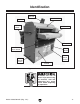
Identification Dust Port Top Cover Cover Lock Knob DC Feed Motor Crank Handle Conveyor Belt Front Elevation Chain Guard Drum Sander Frame On/Off Switch Thermal Circuit Breaker Variable Speed Control Figure 1. Front view, Model G0459. To reduce the risk of serious injury when using this machine, read and understand this entire manual before beginning any operations. Model G0459/G0459P (Mfg.
MACHINE DATA SHEET Customer Service #: (570) 546-9663 · To Order Call: (800) 523-4777 · Fax #: (800) 438-5901 MODEL G0459 12" BABY DRUM SANDER Product Dimensions: Weight.............................................................................................................................................................. 139 lbs. Width (side-to-side) x Depth (front-to-back) x Height........................................................................... 27 x 24 x 27 in. Footprint (Length x Width)..
Main Specifications: Operation Information No Of Sanding Heads....................................................................................................................................... 1 Maximum Board Width.............................................................................................................................. 12 in. Minimum Board Width................................................................................................................................. 2 in.
MACHINE DATA SHEET Customer Service #: (570) 546-9663 · To Order Call: (800) 523-4777 · Fax #: (800) 438-5901 MODEL G0459P 12" BABY DRUM SANDER, POLAR BEAR SERIES® Product Dimensions: Weight.............................................................................................................................................................. 139 lbs. Width (side-to-side) x Depth (front-to-back) x Height........................................................................... 27 x 24 x 27 in.
Main Specifications: Operation Information No Of Sanding Heads....................................................................................................................................... 1 Maximum Board Width.............................................................................................................................. 12 in. Minimum Board Width................................................................................................................................. 2 in.
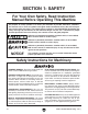
SECTION 1: SAFETY For Your Own Safety, Read Instruction Manual Before Operating This Machine The purpose of safety symbols is to attract your attention to possible hazardous conditions. This manual uses a series of symbols and signal words intended to convey the level of importance of the safety messages. The progression of symbols is described below. Remember that safety messages by themselves do not eliminate danger and are not a substitute for proper accident prevention measures.
WEARING PROPER APPAREL. Do not wear clothing, apparel or jewelry that can become entangled in moving parts. Always tie back or cover long hair. Wear non-slip footwear to avoid accidentalslips,whichcouldcauselossofworkpiececontrol. hAzARdOus dusT. Dust created while using machinery may cause cancer, birth defects, or long-term respiratory damage.
Additional Safety for Drum Sanders FEEDING STOCK. Do not stand in the direct path of a workpiece at the infeed end when feeding your stock. Never sand more than one piece of stock at a time. DO NOT jam the workpiece into the machine during operation. Firmly grasp the workpiece in both hands and ease it into the machine using light pressure. MINIMUM STOCK DIMENSIONS. Do not sand any stock thinner than 1⁄ 8", narrower than 2", or shorter than 8".
SECTION 2: POWER SUPPLY Availability Circuit Requirements Before installing the machine, consider the availability and proximity of the required power supply circuit. If an existing circuit does not meet the requirements for this machine, a new circuit must be installed. To minimize the risk of electrocution, fire, or equipment damage, installation work and electrical wiring must be done by an electrican or qualified service personnel in accordance with all applicable codes and standards.
Grounding & Plug Requirements This machine MUST be grounded. In the event of certain malfunctions or breakdowns, grounding reduces the risk of electric shock by providing a path of least resistance for electric current. This machine is equipped with a power cord that has an equipment-grounding wire and a grounding plug (similar to the figure below). The plug must only be inserted into a matching receptacle (outlet) that is properly installed and grounded in accordance with all local codes and ordinances.
SECTION 3: SETUP Unpacking to reduce your risk of serious injury, read this entire manual bEfORE using machine. Wear safety glasses during the entire setup process! Your machine was carefully packaged for safe transportation. Remove the packaging materials from around your machine and inspect it. If you discover any damage, please call us immediately at (570) 546-9663 for advice. Save the containers and all packing materials for possible inspection by the carrier or its agent.
Site Considerations Weight Load Physical Environment Refer to the Machine Data Sheet for the weight of your machine. Make sure that the surface upon which the machine is placed will bear the weight of the machine, additional equipment that may be installed on the machine, and the heaviest workpiece that will be used. Additionally, consider the weight of the operator and any dynamic loading that may occur when operating the machine.
Mounting The base of this machine has holes that allow it to be mounted to a workbench. We strongly recommend that you mount your machine to a workbench to prevent it from moving during operation. An unexpected movement could result in an injury or property damage. The strongest mounting option is a "Through Mount" where holes are drilled all the way through the workbench, and hex bolts, washers, and hex nuts are used to secure the drum sander to the workbench.
Dust Collection DO NOT operate the Model G0459/G0459P without an adequate dust collection system. This sander creates substantial amounts of wood dust while operating. Failure to use a dust collection system can result in short and long-term respiratory illness. Recommended CFM at Dust Port: 150 CFM Do not confuse this CFM recommendation with the rating of the dust collector.
Test Run Recommended Adjustments Once the assembly is complete, test run your machine to make sure it runs properly. If, during the test run, you cannot easily locate the source of an unusual noise or vibration, stop using the machine immediately, then review the Troubleshooting on Manual Page 23. If you still cannot remedy a problem, contact our Tech Support at (570) 546-9663 for assistance.
SECTION 4: OPERATIONS Operation Overview The purpose of this overview is to provide the novice machine operator with a basic understanding of how the machine is used during operation, so the machine controls/components discussed later in this manual are easier to understand. Due to the generic nature of this overview, it is not intended to be an instructional guide.
Basic Controls Refer to Figure 11 and the following descriptions to become familiar with the basic controls of this machine. A. Variable Speed Knob: Adjusts feed rate from 2.47–17.3 FPM. Rotate clockwise to increase feed speed, rotate counterclockwise to decrease feed speed. B. Hand Crank: Used to raise or lower the conveyor table to control depth of cut. Each full rotation of the hand crank raises or lowers the conveyor table approximately 0.027" (0.69 mm).
Sanding Tips • Replace the sandpaper with a higher grit to achieve a finer finish. • Raise the table with a maximum of ⁄4 turn of the crank handle until the workpiece is the desired thickness. 1 Stock Inspection and Requirements Some workpieces are not safe or may require modification before they are safe to sand.
Depth of Cut The optimum depth of cut will vary based on the type of wood, feed rate, and sandpaper grit. Under most sanding conditions, the depth should not exceed 0.006" (0.15 mm) (approx. 1⁄4 turn of the handwheel). Each full turn of the crank handle raises the conveyor table approximately 0.027" (0.69 mm). Attempts to remove too much material can cause jamming, wood burning, rapid paper wear or tearing, poor finish, belt slippage, and motor damage. To set the depth of cut: 1.
Variable Speed The variable speed knob allows you to increase the feed rate from 2.47–17.3 FPM. The correct speed to use depends on the type of stock you are using (hardwood vs. softwood) and the stage of finish you are at with that workpiece. As a general rule, a slower feed rate sands the surface smoother, but runs the risk of burning the wood; a faster feed rate removes material faster, but runs the risk of overloading the motor.
Choosing Sandpaper There are many types of sanding belts to choose from. We recommend aluminum oxide for general workshop environments. Below is a chart that groups abrasives into different classes, and shows which grits fall into each class. Grit Class 36 Extra Coarse Rough sawn boards, thickness sanding, and glue removal. 12 3/4" Usage 60 Coarse Thickness sanding and glue removal. 80–100 Medium planer Removing marks and initial finish sanding. 120–180 Fine 4.
SECTION 5: ACCESSORIES Some aftermarket accessories can be installed on this machine that could cause it to function improperly, increasing the risk of serious personal injury. To minimize this risk, only install accessories recommended for this machine by Grizzly. NOTICE Refer to the newest copy of the Grizzly Catalog for other accessories available for this machine. Aluminum Oxide Hook & Loop Sanding Rolls, 3" x 50' H4422—60 Grit: Use for thickness sanding and glue removal.
SECTION 6: MAINTENANCE Lubrication Always disconnect power to the machine before performing maintenance. Failure to do this may result in serious personal injury. Schedule For optimum performance from your machine, follow this maintenance schedule and refer to any specific instructions given in this section. Daily Check: • Loose mounting bolts. Worn switch. • • Worn or damaged cords or plugs. • Damaged V-belt. • Any other unsafe condition.
Pillow Block Bearings These must be lubricated every 20 hours of operation. Use a grease gun to pump one or two shots of a high-quality grease into each grease fitting (Figure 22), located on the top of each pillow block bearing. Failure to routinely inspect your drum sander for damage and wear could result in unsatisfactory work results, premature component or machinery failure, or operator injury. We recommend you create a checklist for routine inspection and maintenance.
SECTION 7: SERVICE Review the troubleshooting and procedures in this section if a problem develops with your machine. If you need replacement parts or additional help with a procedure, call our Technical Support at (570) 546-9663. Note: Please gather the serial number and manufacture date of your machine before calling. Troubleshooting Motor & Electrical Symptom Possible Cause Possible Solution Machine does not 1. Plug or receptacle is at fault or wired 1.
Sanding Operations Symptom Possible Cause Possible Solution 1. Seal all leaks, size ducts correctly, eliminate bends, and refer to Dust Collection Basics Handbook (ISBN 0-9635821-2-7) for further recommendations. 2. Make sure all hot lines and grounds are operational and have correct voltage on all legs. 3. Replace bad belt, align pulleys, and re-tension. 4. Correct motor wiring (see Page 45). 5. Test power plug and receptacle for good contact and correct wiring. 6. Replace loose pulley and shaft. 7.
Symptom Shor t lifespan. Conveyor under load. Possible Cause V- belt 1. Pulleys not aligned correctly. 2. Improperly tensioned. slips 1. Conveyor is too loose. 2. Too much load. Conveyor tracks to 1. Conveyor tracking is incorrect. one side; conveyor hits the roller cover. Possible Solution 1. Align pulleys (Page 31). 2. Properly tension V-belts (Page 30). 1. Tension conveyor (Page 32). 2. Decrease load. 1. Track the conveyor so it runs straight (Page 32). Workpiece pulls 1.
Gauge Blocks V-Belt Service Tools Needed: Qty 6' Long 2x4......................................................... 1 Miter Saw (or Circular Saw)................................ 1 Jointer................................................................. 1 Table Saw........................................................... 1 Tools Needed: Qty Hex Wrench 6mm............................................... 1 Wrench 12mm.................................................... 1 Straightedge........................
Pulley Alignment To adjust V-belt tension: 1. DISCONNECT POWER TO THE SANDER! 2. Open the rear panel. 3. Loosen the motor mount bolts and raise or lower the motor bracket, as shown in Figure 26, to loosen or tighten the V-belt. 4. Tighten the motor mount bolts and replace the rear panel. Pulley alignment is another important factor in power transmission and belt life. The pulleys should be parallel to each other and in the same plane (coplaner) for optimum performance.
Conveyor Tensioning & Tracking 2. Turn both of the conveyor adjustment bolts counterclockwise one full turn at a time until the conveyor belt no longer slips during operation. —If the conveyor starts tracking to one side, immediately turn the drum sander OFF and perform the tracking instructions. Tools Needed: Qty Wrench 19mm.................................................... 1 Phillips Head Screwdriver #2.............................
Drum Adjustments The drums can be adjusted in fine increments at the pillow block bearings and in larger increments by using the table lift screws (Page 37). Tools Needed: Qty Hex Wrench 4mm............................................... 1 Wrench 19mm.................................................... 1 Wrench 10mm.................................................... 1 Socket 14mm...................................................... 1 Measuring Tape..................................................
4. Place the gauge blocks on the conveyor table and position them under the pressure rollers, as shown in Figure 32. 2. Rotate the setscrews 1⁄8 of a turn clockwise to raise the pillow block bearings (see Figure 31). Note: Turn all setscrew sets an equal amount. Figure 32. Gauge blocks positioned under pressure rollers and sanding drum. 5. Raise the table until the gauge blocks just touch the bottom of the sanding drum.
Pressure Roller Height Tools Needed: Qty Wrenches/Sockets 10mm................................... 1 Gauge Blocks (see Page 30)............................. 2 Factory Setting: Distance Below Sanding Drum.......0.080" (2mm) The pressure rollers are factory set at 0.080" (2mm) below the bottom of the sanding drum and are fully adjustable either up/down with the four lower adjustment bolts (Figure 34). After the adjustment has been made, always lock the jam nuts against the bottom to prevent them from moving.
5. Turn the crank handle three full rotations (counting from the point of actual table movement so handwheel freeplay does not affect your count) to lower the table so the gauge blocks are below the pressure rollers, as shown in Figure 36. Figure 37. Pressure rollers set correct distance below bottom of sanding drum. 9. Tighten the jam nuts (Figure 34) to lock the adjustment. Figure 36. Gauge blocks below pressure rollers.
Table Lift Screws Tools Needed: Qty Hex Wrench 6mm............................................... 1 Wrench/Socket 12mm........................................ 1 Chalk, Correction Fluid, or Paint........................ 1 Phillips Head Screwdriver #2............................. 1 Flat Head Screwdriver........................................ 1 The table lift screws are connected by a chain and driven by the crank handle.
Conveyor Belt Replacement Tools Needed: Qty Hex Wrench 6mm............................................... 1 Wrench/Socket 19mm........................................ 1 Wrenches/Sockets 14mm................................... 2 Wrench/Socket 12mm........................................ 1 Wrench 10mm.................................................... 1 Phillips Head Screwdriver #2............................. 1 Measuring Tape.................................................. 1 Gauge Blocks (see Page 30)....
6. Remove the rear pressure roller (4 hex bolts and 4 flat washers) along with the brackets, compression springs, and spring plates shown in Figure 42. 9. Remove the sanding drum (4 lock nuts and 4 flat washers) and V-belt (Figure 44). Spring Plate Compression Spring Bracket NEW PHOTO Figure 42. Rear pressure roller components. 7. Remove the rear panel. 8. Loosen the hex bolts securing the motor bracket to the frame, raise the motor and remove the V-belt from the motor pulley (see Page 31 for help).
11. Mark the top of the table lift screws with arrows (all pointing in same direction) and mark the screws with liquid correction fluid above the mounting bracket (Figure 46). Later, when you reassemble the conveyor table, you can use these marks to reset the table height close to the current position. 15. Disconnect the conveyor feed motor wires from the circuit board. 16. Remove the scale pointer.
18. Lay the conveyor table on the edge of a workbench so the conveyor motor can hang freely. 19. Remove the conveyor motor (4 cap screws) from the conveyor motor cover, and remove the conveyor motor cover from left rear roller bracket (3 cap screws and 3 flat washers). Table Cap Screws Flat Washer Flat Washer Cap Screw Left Rear Roller Bracket Cap Screw Conveyor Motor Cover Conveyor Motor Figure 50. Removing conveyor motor and rear roller bracket (not all components shown for clarity). 20.
33. Before re-installing the gear box cover, try raising and lowering the conveyor table with the crank handle. If the helical gears (see Figure 52) are not engaged, the crank handle will only raise the table. Changing Motor Brushes If this happens, loosen the crank handle mounting bolts, and move the helical gear around until the teeth mesh with the helical crank handle gear, then secure the crank handle. Tools Needed: Qty Flat Head Screwdriver........................................
machine SECTION 8: WIRING These pages are current at the time of printing. However, in the spirit of improvement, we may make changes to the electrical systems of future machines. Compare the manufacture date of your machine to the one stated in this manual, and study this section carefully. If there are differences between your machine and what is shown in this section, call Technical Support at (570) 546-9663 for assistance BEFORE making any changes to the wiring on your machine.
Electrical Components Figure 54. Feed motor. Figure 57. Capacitor. Figure 55. Drum motor wiring. Figure 58. Variable speed control and circuit board. Figure 56. Switch box wiring. -44- READ ELECTRICAL SAFETY ON PAGE 43! Model G0459/G0459P (Mfg.
Wiring Diagram FEED MOTOR (Figure 54) ON/OFF SWITCH (Figure 56) NO 2 DC CIRCUIT BOARD 6 3 (Figure 58) 5 FFO Ground VARIABLE SPEED CONTROL 1 THERMAL CIRCUIT BREAKER (Figure 56) (Figure 58) Neutral Hot S Capacitor 300MFD 125VAC Ground 115 VAC Ground DRUM MOTOR 5-15 Plug (As Recommended) (Figure 55) The motor wiring shown here is current at the time of printing, but it may not match your machine. Always use the wiring diagram inside the motor junction box. Model G0459/G0459P (Mfg.
SECTION 9: PARTS Frame 29 10 14 225 29 14-1 211 44 101 12-2 117 118 103 104 107 12 29 108 8-7 8-4 110 119 119 113 12-1 109 11 29 115 29 6 8-7 7-1 16V2 9 20V2 31-1 29 44 31V2 45 20-4V2 100 32V3 54-1 28 55 54 223 4 24 134 29 40 34 40 34 22 22 24 135 136 134 135 136 7-2 2 20-1 212V3 209 138 209-1 57 29 132 7-1 7-2 29 3 134 6 8-7 6 8-7 22 24 134 133 135 8-6 6 8-7 17 17 18 19 8-7 8-1 112V2 4 20-6 20-2 20-5 20-3 8-1 8-2 8-7 8-1 99 20-7 8-7 8-3 8-5 114
Frame Parts List REF PART # DESCRIPTION REF PART # DESCRIPTION 1 2 3 4 4 5 5-1 6 7-1 7-2 8-1 8-2 8-3 8-4 8-5 8-6 8-7 9 10 10 11 12 12-1 12-2 13 14 14 14-1 15 15 16V2 16V2 17 18 19 20V2 20-1 20-2 20-3 20-4V2 20-5 20-6 20-7 22 24 28 29 30-1V2 30-2V2 30-3V2 30-4V2 30-5 31V2 31-1 32V3 P0459001 PN02 PW07 P0459004 P0459P004 P0459005 PCAP09 P0459006 P0459007-1 P0459007-2 P0459008-1 P0459008-2 P0459008-3 P0459008-4 PK06M P0459008-6 PW01 P0459009 P0459010 P0459P010 P0459011 P0459012 PS41 PN12 G2977 P0459014 P
Drum 23 25 89 89-1 90 89-1 89 26 86 86 85 27 74 17 82 81 94 25 89-1 90 89-1 73 89 42 26 70 88 74 23 89 88 85 88 71 74 73 73 70 86 88 98 74 73 85 86 85 92-1 81 82 27 92 REF PART # DESCRIPTION REF PART # DESCRIPTION 17 23 25 26 27 42 70 71 73 74 81 SET SCREW 1/4-20 X 3/8 HEX BOLT 1/4-20 X 5/8 HEX NUT 1/4-20 SPRING PLATE ADJUST PLATE KEY 5 X 5 X 20 PRESSURE ROLLER SANDING DRUM EXT RETAINING RING 19MM BUSHING PILLOW BLOCK BEARING 82 85 86 88 89 89-1 90 92 92-1 94 98
Conveyor 52 66 57 79 74 80 77 50-2 58 57 36 17 35 127 65-1 61 69 60 51-1V2 35 64 25 64 74 60 61 50-1 51-3V2 51V2 57 125 64 35 78 124 51-2V4 65V3 102 126 64 125 58 76 76 127 78 63 83 123 50-1 38V2 39V4 39V4-10 39V4-15 39V4-16 39V4-13 39V4-14 39V4-11 39V4-1 39V4-2 39V4-14 39V4-12 39V4-13 39V4-9 39V4-3 39V4-4 39V4-6 39V4-7 39V4-7 39V4-5 39V4-5 Model G0459/G0459P (Mfg.
Conveyor Parts List REF PART # DESCRIPTION REF PART # DESCRIPTION 17 25 35 36 38V2 39V4 39V4-1 39V4-2 39V4-3 39V4-4 39V4-5 39V4-6 39V4-7 39V4-8 39V4-9 39V4-10 39V4-11 39V4-12 39V4-13 39V4-14 39V4-15 39V4-16 50-1 50-2 51V2 51-1V2 PSS03 PN05 PN03 P0459036 P0459038V2 P0459039V4 PS56M PLW02M P0459039V4-3 P0459039V4-4 P6003ZZ P0459039V4-6 P6000ZZ PR06M P0459039V4-9 P0459039V4-10 P0459039V4-11 P0459039V4-12 P0459039V4-13 P0459039V4-14 P0459039V4-15 PS19M P0459050-1 P0459050-2 P0459051V2 P0459051-1V2 SET S
WARRANTY CARD Name _____________________________________________________________________________ Street _____________________________________________________________________________ City _______________________ State _________________________ Zip _____________________ Phone # ____________________ Email _________________________________________________ Model # ____________________ Order # _______________________ Serial # __________________ The following information is given on a voluntary basis.
FOLD ALONG DOTTED LINE Place Stamp Here GRIZZLY INDUSTRIAL, INC. P.O.
WARRANTY AND RETURNS WARRANTY AND RETURNS Grizzly Industrial, Inc. warrants every product it sells for a period of 1 year to the original purchaser from the date of purchase. This warranty does not apply to defects due directly or indirectly to misuse, abuse, negligence, accidents, repairs or alterations or lack of maintenance.
Buy Direct and Save with Grizzly ® – Trusted, Proven and a Great Value! ~Since 1983~ Visit Our Website Today For Current Specials! ORDER 24 HOURS A DAY! 1-800-523-4777