MODEL G1095/G1096 1-HP POWER FEEDER with 4-ROLLER & 4-SPEED OWNER'S Manual Copyright © MAY, 2008 By Grizzly Industrial, Inc. REVISED JULY, 2008. Warning: No portion of this manual may be reproduced in any shape Or form without the written approval of Grizzly Industrial, inc.
4HIS MANUAL PROVIDES CRITICAL SAFETY INSTRUCTIONS ON THE PROPER SETUP OPERATION MAINTENANCE AND SERVICE OF THIS MACHINE EQUIPMENT &AILURE TO READ UNDERSTAND AND FOLLOW THE INSTRUCTIONS GIVEN IN THIS MANUAL MAY RESULT IN SERIOUS PERSONAL INJURY INCLUDING AMPUTATION ELECTROCUTION OR DEATH 4HE OWNER OF THIS MACHINE EQUIPMENT IS SOLELY RESPONSIBLE FOR ITS SAFE USE 4HIS RESPONSIBILITY INCLUDES BUT IS NOT LIMITED TO PROPER INSTALLATION IN A SAFE ENVIRONMENT PERSONNEL TRAINING AND USAGE AUTHORIZATION PROPER INS
Table of Contents INTRODUCTION................................................ 2 Foreword......................................................... 2 Contact Info.................................................... 2 Functional Overview....................................... 2 Identification.................................................... 7 SECTION 4: OPERATIONS............................ 19 Operation Safety........................................... 19 Basic Use and Care...............................
INTRODUCTION Foreword Functional Overview We are proud to offer the Model G1095/G1096 1HP Power Feeder. This machine is part of a growing Grizzly family of fine woodworking machinery. When used according to the guidelines set forth in this manual, you can expect years of trouble-free, enjoyable operation and proof of Grizzly’s commitment to customer satisfaction.
MACHINE DATA SHEET Customer Service #: (570) 546-9663 · To Order Call: (800) 523-4777 · Fax #: (800) 438-5901 MODEL G1095 POWER FEEDER 4 ROLLER / 4 SPEED, SINGLE-PHASE EgdYjXi 9^bZch^dch/ Weight.............................................................................................................................................................. 144 lbs. Length/Width/Height...........................................................................................................
DeZgVi^dc >c[d No. Of Feed Speeds......................................................................................................................................... 4 Feed Speeds........................................................................................................................ 13, 26, 33, 66 FPM Swing.................................................................................................................................................... 360 deg. Vertical Movement........
MACHINE DATA SHEET Customer Service #: (570) 546-9663 · To Order Call: (800) 523-4777 · Fax #: (800) 438-5901 MODEL G1096 POWER FEEDER 4 ROLLER / 4 SPEED, 3PHASE EgdYjXi 9^bZch^dch/ Weight.............................................................................................................................................................. 144 lbs. Length/Width/Height...........................................................................................................43-1/4 x 23-1/2 x 29-1/2 in.
DeZgVi^dc >c[d No. Of Feed Speeds......................................................................................................................................... 4 Feed Speeds........................................................................................................................ 13, 26, 33, 66 FPM Swing.................................................................................................................................................... 360 deg. Vertical Movement........
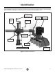
Identification Refer to Figure 1 and your power feeder to familiarize yourself with the controls, features, and terminology used in this manual. Doing so will make setup, use, and any future maintenance easy. Vertical Travel Handcrank Vertical Travel Lock Upper Elbow Joint Lock Motor Assembly Horizontal Travel Lock Lower Elbow Joint Lock Horizontal Handcrank Gearbox Oil Plug Rotary Movement Lock Power Feeder Swivel Lock Figure 1. Controls and features.
3%#4)/.
3AFETY )NSTRUCTIONS FOR -ACHINERY /.,9 !,,/7 42!).%$ !.$ 02/0 %2,9 350%26)3%$ 0%23/..%, 4/ /0%2!4% -!#().%29 BV`Z hjgZ deZgVi^dc ^chigjXi^dch VgZ hV[Z VcY XaZVgan jcYZghiddY# +%%0 #(),$2%. !.$ 6)3)4/23 !7!9 @ZZe Vaa X]^aYgZc VcY k^h^idgh V hV[Z Y^h" iVcXZ [gdb i]Z ldg` VgZV# -!+% 7/2+3(/0 #(),$02//& JhZ eVYadX`h! bVhiZg hl^iX]Zh! VcY gZbdkZ hiVgi hl^iX] `Znh# .%6%2 ,%!6% 7(%. -!#().% )3 25..).
Additional Safety for Power Feeders 1. SAFETY ACCESSORIES. Always use appropriate machine guards. 2. TOOL SPEED. Make sure all cutting tools are rotating at the operating speed before feeding the workpiece. 3. 4. FEEDING SPEED. DO NOT overload the cutting tool by feeding too quickly. The cutting tool will perform better and be safer working at the rate for which it was designed. HAND SAFETY. Keep hands away from rotating parts on the feeder and the cutting tool.
SECTION 2: CIRCUIT REQUIREMENTS 220V Single-Phase Operation (G1095) Power Connection Device The type of receptacle required to connect your machine to power depends on the type of service you currently have or plan to install. We recommend using the plug and receptacle shown in Figure 2. Serious personal injury could occur if you connect the machine to power before completing the setup process. DO NOT connect the machine to the power until instructed later in this manual.
220V Three-Phase Operation (G1096) Power Connection Device The type of plug and receptacle required to connect your machine to power depends on the type of service you currently have or plan to install. We recommend using the configuration shown in Figure 3. Serious personal injury could occur if you connect the machine to power before completing the setup process. DO NOT connect the machine to the power until instructed later in this manual.
SECTION 3: SETUP Setup Safety This machine presents serious injury hazards to untrained users. Read through this entire manual to become familiar with the controls and operations before starting the machine! Wear safety glasses during the entire setup process! This machine and its components are very heavy. Get lifting help or use power lifting equipment such as a forklift to move heavy items.
Inventory The following is a description of the main components shipped with your machine. Lay the components out to inventory them. If any nonproprietary parts are missing (e.g. a nut or a washer), we will gladly replace them; or for the sake of expediency, replacements can be obtained at your local hardware store. Note: If you can't find an item on this list, check the mounting location on the machine or examine the packaging materials carefully.
Hardware Recognition Chart Model G1095/G1096 1-HP Power Feeder -15-
Clean Up Assembly The unpainted surfaces are coated with a waxy oil to prevent corrosion during shipment. Remove this protective coating with a solvent cleaner or degreaser, such as shown in Figure 6. For thorough cleaning, some parts must be removed. For optimum performance, clean all moving parts or sliding contact surfaces. Avoid chlorine-based solvents, such as acetone or brake parts cleaner that may damage painted surfaces.
Base Mounting Whichever way you mount your power feeder, you must be able to use the handcranks and lock levers to position the rubber wheels parallel with the table surface and 1⁄8" lower than the thickness of your workpiece. Position the power feeder on the table top to determine where to drill your base mounting holes, so you can maximize power feeder swing and adjustment options. Also, you must be able to point the power feeder slightly towards the machine fence (Figure 9).
Through-Bolt Mounting Direct Mounting We recommend that you mount your new power feeder to the machine table with through bolts, nuts, and washers (Figure 10). This option will give the most rigidity and clamping strength to prevent the feeder base from twisting out of alignment during use. However, if under-table support webs interfere with washer or nut locations under the table, you must use an optional clamping kit, or drill and thread holes directly into the table as described in Direct Mounting.
Test Run 4. Adjust and lock the power feeder so the wheels are held approximately one inch above the table and nothing will interfere with wheel rotation. You MUST assemble all guards, fences, and hold-downs before starting your machine or power feeder. Failure to heed this warning could result in amputation or death! Loose hair and clothing could get caught in machinery and cause serious personal injury. Keep loose clothing rolled up and long hair tied up and away from machinery. 5.
SECTION 4: OPERATIONS Operation Safety To reduce the risk of serious injury when using this machine, read and understand this entire manual before beginning any operations. Damage to your eyes and lungs could result from using woodworking machinery without proper protective gear. Always wear safety glasses and a respirator when operating this machine. Basic Use and Care You MUST assemble all guards, fences, and hold-downs before starting your machine or power feeder.
Changing Speeds 3. Refer to the feed rate list below to find the gear combination required for your chosen feed rate. 13 Ft Per Min: A, 25 Tooth + B, 40 Tooth. Always disconnect power to the machine before performing installation or maintenance. Failure to do this may result in serious personal injury. 26 Ft Per Min: A, 40 Tooth + B, 25 Tooth. 33 Ft Per Min: A, 25 Tooth + B, 40 Tooth. 66 Ft Per Min: A, 40 Tooth + B, 25 Tooth.
SECTION 5: MAINTENANCE • Always disconnect power to the machine before performing maintenance. Failure to do this may result in serious personal injury. Every 40 hours of use, or once every two weeks, wipe clean and lubricate the wheel grease fittings (Figure 15) with one pump from a grease gun filled with automotive grade GL-2 grease. Schedule For optimum performance from your machine, follow this maintenance schedule and refer to any specific instructions given in this section.
SECTION 6: SERVICE Review the troubleshooting and procedures in this section to fix or adjust your machine if a problem develops. If you need replacement parts or you are unsure of your repair skills, then feel free to call our Technical Support at (570) 546-9663. Troubleshooting Motor & Electrical Symptom Possible Cause Possible Solution Motor will not start. 1. Check power supply for proper voltage. 1. Low voltage. 2. Open circuit in motor or loose connections. 2.
Wheel Replacement Cap Screw Always disconnect power to the machine before performing installation or maintenance. Failure to do this may result in serious personal injury. If you damage one or more wheels or they are worn out, you can easily replace the wheels. Tools Needed Qty Hex Wrench 5mm............................................... 1 Figure 17. Wheel cap screws. 3. Swap the old wheel with the new one. 4.
SECTION 7: WIRING These pages are current at the time of printing. However, in the spirit of improvement, we may make changes to the electrical systems of future machines. Study this diagram carefully. If you notice differences between your machine and these wiring diagrams, call Technical Support at (570) 546-9663 for assistance. Electrical Safety Instructions 1. CIRCUIT REQUIREMENTS. You MUST follow the CIRCUIT REQUIREMENTS given on Page 9.
Electrical BdYZa <&%.* EdlZg ;ZZYZg ''%K H^c\aZ"E]VhZ L^g^c\ 9^V\gVb View this page in color at www.grizzly.com. ) H^YZ 7 ' G & , - + H * J && &' &% L . N &* &+ &) &. '% '( K ') '' & &( O &- ) &, I '& (*B;9 '*%K68 ( Ild HeZZY Bdidg 9^gZXi^dc Hl^iX] 8VeVX^idg H^YZ 6 ''%K Ild HeZZY Bdidg
BdYZa <&%.+ EdlZg ;ZZYZg ''%K I]gZZ"E]VhZ L^g^c\ 9^V\gVb K^Zl i]^h eV\Z ^c Xdadg Vi lll#\g^ooan#Xdb# H^YZ 6 ( ' G & + H * J && &' &% L . N &* &+ &) '% K ') O &- '' & &( ) &, I '&
-28- &,%"+ &'% &', &-& &*& &*' &'% &*( &(% &'' &'( &(&(& &+) &&, &'* &&% &&& &&. &+( &') &-. &%* &%. &+( &&) &-, &+( &&) &-, &'% &(. &&- &(' &+- &.' &%- &&, &') &-. &&% &&+ &+( &&& &&) &&+ &-, &&' &&( &.( &&' &&( &%. &%, &%( &-&&, &-&') &'+ &'* &'&&% &-. &'+ &%' &&+ &&' &&& &&. &'. &%- &&( &.' &%, &,. &-&'* &,* &,, &'+ &&+ &%) &') &-. &&% &%* &&&(, &(+ &&' &&& &'* &&( &-&%' &%( &&, &*, &*- &'+ &%) &)) &&&%& &*% &(&&- &,%"& &,%"' &(, &(+ &&- &+' &** &*+ &,%"* <&%.
Power Feeder Parts List REF PART # DESCRIPTION REF PART # DESCRIPTION 101 102 103 104 105 107 108 109 110 111 112 113 114 116 117 118 119 120 122 123 124 125 126 127 128 129 130 131 132 136 137 138 139 P6203 P1096102 P1096103 P1096104 P1096105 P1096107 P1096108 P1096109 P1096110 P1096111 PLW03M PSB01M PLW04M P1096116 P1096117 PR58M P1096119 PR47M PW01 PN09M P1096124 P1096125 P1096126 P1096127 P1096128 PORP015 P1096130 P1096131 PSS01M P1096136 P1096137 P1096138 P1096139 BALL BEARING 6203 GREASE FITTI
Base '*& '*) '%) '%) '** '*, ''& '%( '%( '&- ''- '*' '%' '&' '%, '%+ '%* '(& '%' '%' '%( '%) '') ''+ '&) '&% '&' '*) '%% '%( ')& '() '*. ')% ''* '&. '%' ''% ''. ''' '*+ '%) '*& '** Base Parts List REF PART # DESCRIPTION REF PART # DESCRIPTION 200 202 203 204 205 206 207 210 212 214 218 219 220 221 222 224 P1096200 P1096202 PW06M P1096204 PSB24M P1096206 P1096207 P1096210 PSB50M P1096214 P1096218 PSS09M PLW04M P1096221 PN03M P1096224 COLUMN BASE STUD M12-1.
7!22!.
;DA9 6ADC< 9DII:9 A>C: EaVXZ HiVbe =ZgZ '2)::,9 ).$5342)!, ).# 0 / "/8 "%,,).
WARRANTY AND RETURNS 7!22!.49 !.$ 2%452.
"UY $IRECT AND 3AVE WITH 'RIZZLY® n 4RUSTED 0ROVEN AND A 'REAT 6ALUE 6ISIT /UR 7EBSITE 4ODAY !ND $ISCOVER 7HY 'RIZZLY® )S 4HE )NDUSTRY ,EADER s 3%#52% /2$%2).' s /2$%23 3()00%$ 7)4(). (/523 s % -!), 2%30/.3% 7)4(). /.