
Use and Care Manual
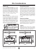
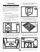
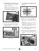
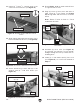
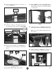
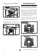
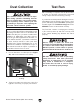
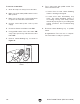
Table Of Contents

-20-
Model T28780 T28781 (Mfd. Since 04/20)
3. Attach leg assemblies as shown below with
(2) long braces, (8)
5
⁄16
"
-18 x
1
⁄2
"
flange bolts
and (8)
5
⁄16" external tooth washers
.
4. Install (2) long braces (see Figure 14) at top
of leg assemblies with (8)
5
⁄16
"
-18 x
1
⁄2
"
bolts
and (8)
5
⁄16" external tooth washers
.
Assembly
To assemble router table:
1.
Locate two legs (see Figure 12) and attach
with (1) lower short brace at bottom using (4)
5
⁄16
"
-18
x
1
⁄2
" flange bolts and (4)
5
⁄16" external
tooth washers. Repeat with second pair of
legs and (1) lower short brace.
2. Install (4) adjustable feet in bottom of each
leg (see Figure 12).
The machine must be fully assembled before it
can be operated. Before beginning the assembly
process, refer to
Needed for Setup
and gather
all
listed items.
To ensure the assembly process
goes smoothly, first clean any
parts that are
cov-
ered or coated in heavy-duty rust preventative (if
applicable).
5. Place table (see Figure 15) upside-down on
flat surface, then attach (2) upper short brac-
es to table with (4)
5
⁄16
"
-18 x
1
⁄2
"
flange bolts.
6. Place table on stand, as shown below, and
attach with (8)
5
⁄16
"
-18 x
1
⁄2
"
flange bolts
and
(8)
5
⁄16" external tooth washers
.
Figure 12. Legs assembled and feet installed.
Legs
Brace
Feet
Figure 13. Leg assemblies attached.
Long Braces
Figure 14. Long braces installed at top of legs.
Figure 15. Upper short braces attached to table.
Braces
Figure 16. Router table attached to stand.
Table
Stand
Bolts
x 8
x 8
x 8
x 8
x 4