
Use and Care Manual
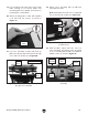
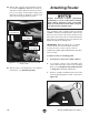
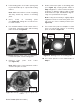


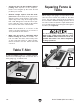
Table Of Contents

Model T28048 (Mfd. Since 06/17)
-19 -
19. Lay mounting plate with plate insert inside
table opening on set screws. Make sure
mounting plate faces upward. (Top surface of
mounting has countersinks.)
20. Attach mounting plate to table with (4) M6-1
x 35 flat head cap screws, as shown in
Figure 19.
21. Lay fence assembly on table and insert (2)
M8-1.25 x 92 knob bolts with spacers through
fence and slots in table (see Figure 20).
22. Attach fence assembly with (2) M8-1.25
extra-wide hex nuts.
Note: Extra-wide hex nuts fit into channeled
slot on bottom side of table (see Figure 21).
Figure 21. Inserting extra-wide hex nut into
channeled slot.
Figure 19. Securing mounting plate to table.
Mounting
Plate
Figure 20. Knob bolts and spacers inserted
through fence and table.
Table
Slot
Fence Assembly
Knob
Bolt
Spacer
23. Slide (2) M6-1 square nuts into T-slot on
fence assembly and attach router bit guard
to fence assembly with (2) M6-1 x 15 knurled
thumb screws, as shown in Figure 22.
Channeled
Slot
x 4
Table
Slot
x 2
Figure 22. Attaching router bit guard to fence
assembly.
Fence
Assembly
Square
Nut
Thumb
Screw
Fence
T-Slot
Router
Bit
Guard